
Pushup exercise device

a push-up and exercise device technology, applied in the field of push-up exercise devices, can solve the problems of frictional force, mechanical limitation of range, uneven rotation of the device, etc., and achieve the effect of easy and smooth rotation

Active Publication Date: 2008-05-27
GODBOLD TEMICO R
View PDF7 Cites 54 Cited by
  • Summary
  • Abstract
  • Description
  • Claims
  • Application Information

AI Technical Summary

Benefits of technology

[0010]The present invention provides hand supports for performing pushups on a floor or ground surface. The hand supports can be easily and smoothly rotated about a vertical axis while performing pushups. The hand supports generally comprise a handle, a rotatable base, and handle support.
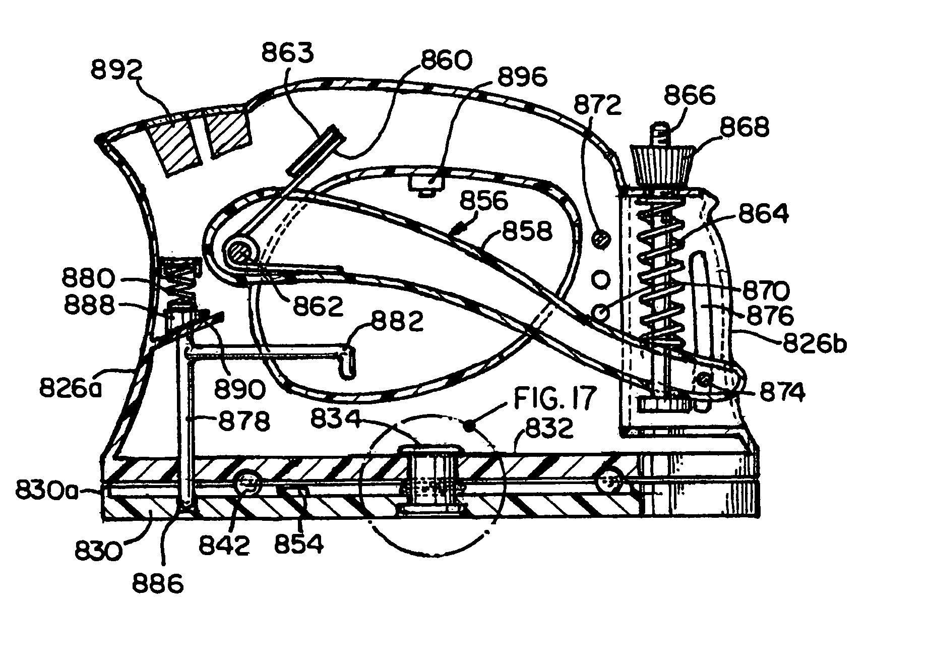
[0016]In yet another embodiment of the invention, the device is easily collapsible to a compact size so that the user can comfortably travel with the device. The handle support is movable from a first, extended position supporting the handle at an elevated position relative to the base, and a second collapsed position. In this embodiment, the support preferably includes a hinge connecting the support to the upper portion of the base so that the support is rotatable between a first extended position, and a second position generally co-planar with the base.

Problems solved by technology

Further, the hand grips are rotatable so that the user can rotate his hands and wrists through a mechanically limited range of motion.
To rotate such devices, the user must overcome the frictional force between the plates, which may be excessive depending on the upper body weight of the user and the coefficient of friction between the plates.
Further, rotation of the device may not be smooth due to variations in the force required to initiate rotation compared to the force required to maintain rotation.
Several of the pushup devices in the prior art provide a handle having a cylindrical profile, which may be comfortable for some users but uncomfortable for others.
In the prior art, the various pushup devices vary greatly in size and complexity.
However, even the smallest devices are prohibitively large to conveniently travel with in a briefcase, handbag or small luggage.

Method used


Image

  • Pushup exercise device
  • Pushup exercise device
  • Pushup exercise device

Examples


Embodiment Construction

[0047]For the purpose of illustrating the invention, there is shown in the accompanying drawings several embodiments of the invention. However, it should be understood by those of ordinary skill in the art that the invention is not limited to the precise arrangements and instrumentalities shown therein and described below.

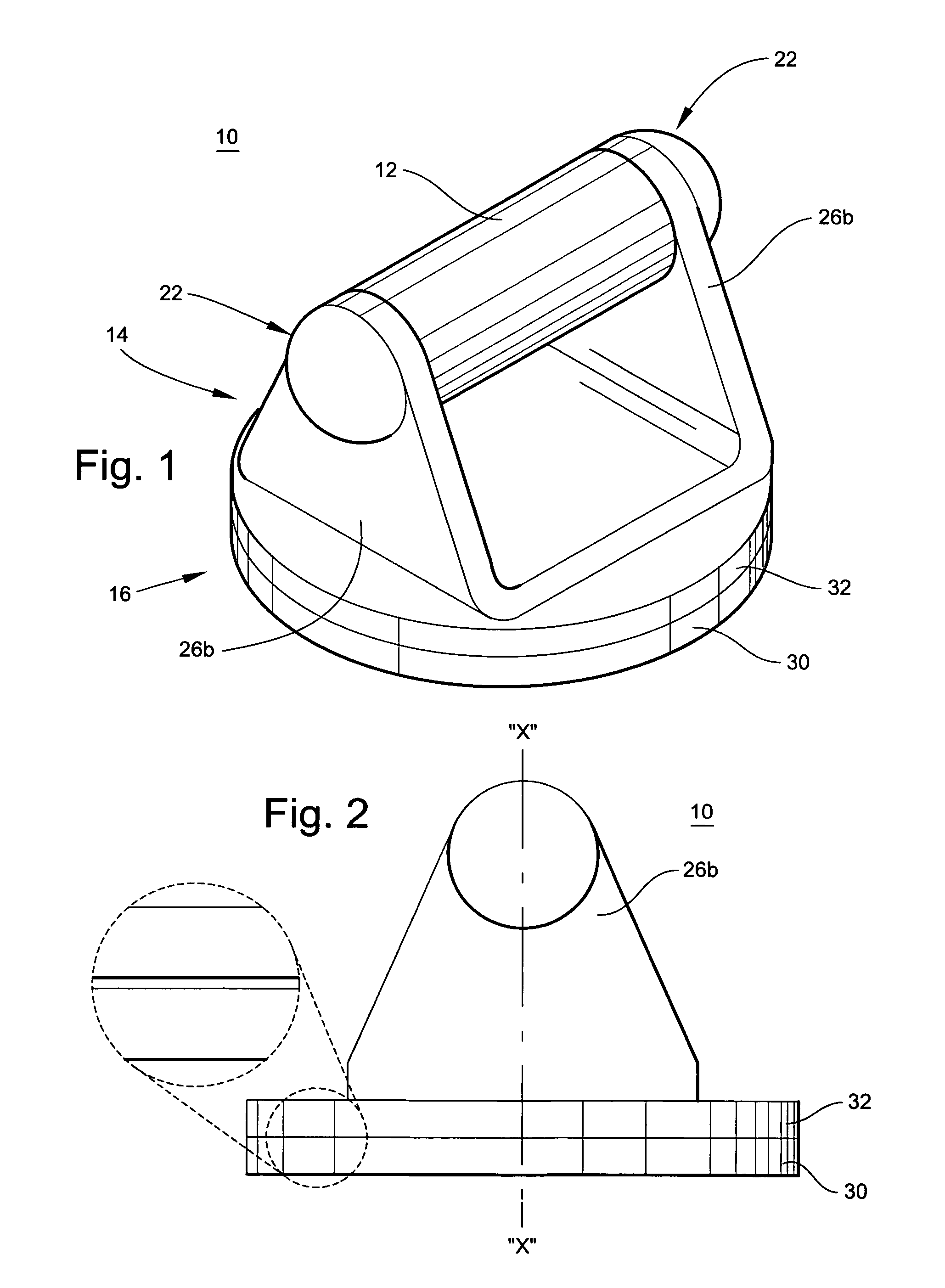
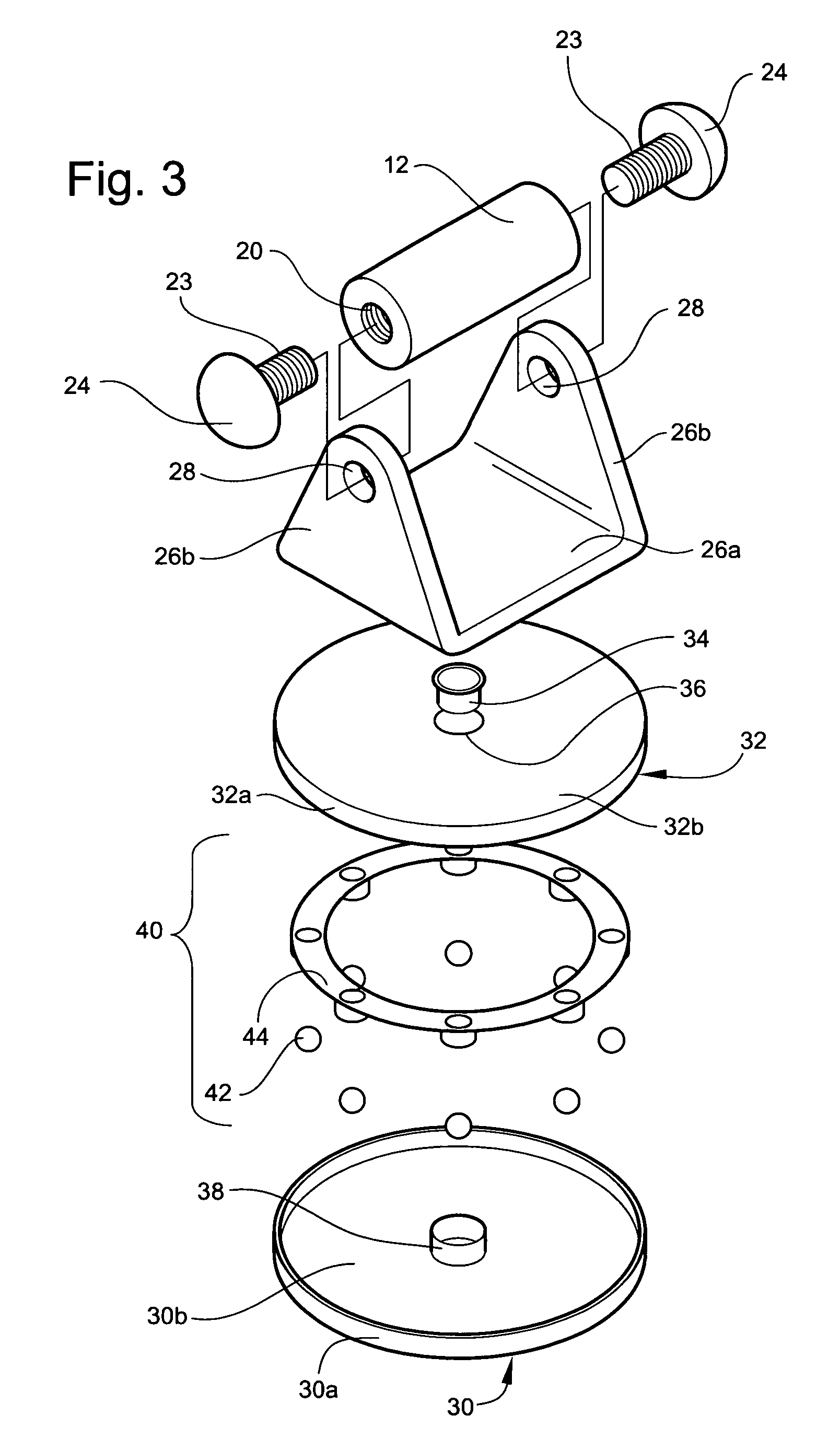
[0048]The pushup device in accordance with preferred embodiments of the present invention is illustrated in FIGS. 1-24 wherein like reference numerals are used throughout to designate like elements.

[0049]A first embodiment of the pushup device, designated generally by reference numeral 10, is shown in FIGS. 1-4. The pushup device 10 generally comprises a handle 12, a rotatable base 16, and a support assembly 14 that connects the handle 12 to the base 16 and supports the handle 12 at an elevated position relative to the base 16. The handle 12 is constructed to be grasped by the user. The base 16 is constructed to rest on the floor or other support surface.

[0050]In t...


PUM


Abstract

Rotatable hand supports for performing advanced pushups on a floor or ground surface. The main handle of the supports has a grip portion constructed to be grasped by a user. The base has a bottom portion adapted to contact the floor, a top portion rotatably connected to the bottom portion, and a bearing assembly supporting the top portion on said bottom portion. A support connects the handle to the top portion of the base and supports the handle at an elevated position relative to the base and above the floor. A hand clutch extends from the main handle and can be squeezed to perform hand-grip exercises simultaneously with a pushup exercise.

Description

[0001]This is a continuation-in-part application of U.S. patent application Ser. No. 10 / 891,645 filed on Jul. 15, 2004 entitled Pushup Exercise Device.FIELD OF THE INVENTION[0002]The present invention relates to an exercise device for performing pushups. More particularly, the present invention relates to hand supports having hand grips that are elevated and rotatable relative to the floor so that the user's comfort is improved and range of motion is extended while performing pushups.BACKGROUND OF THE INVENTION[0003]The conventional pushup exercise has traditionally been used for strengthening arm muscles. A conventional pushup is performed by lying face down with palms to the floor and by pushing the body up and down with the arms.[0004]Many types of handgrip devices are known for performing pushups. For example, Acs et. al, U.S. Pat. No. 3,115,338, disclose handles that are rigidly supported on stationary bases. The handles assist the user performing pushups by providing a more ad...

Claims


Application Information

Patent Timeline
Patent Type & Authority Patents(United States)
IPC IPC(8): A63B26/00
CPCA63B26/003A63B71/06A63B21/00047A63B21/1434A63B21/1469A63B23/12A63B23/14A63B23/16A63B2210/50A63B2220/17A63B2225/20A63B22/14A63B23/1236A63B21/4017A63B21/4035
Inventor GODBOLD, TEMICO R.
Owner GODBOLD TEMICO R
Learn More