Developing apparatus

a technology of developing apparatus and developing chamber, which is applied in the direction of electrographic process apparatus, instruments, optics, etc., can solve the problems of not only being contrary, the compatibility of ghost image faults is difficult, and the fog performance during endurance is reduced, so as to prevent fog, prevent uneven image density, and suppress image faults

Active Publication Date: 2008-05-27
CANON KK
View PDF29 Cites 15 Cited by
  • Summary
  • Abstract
  • Description
  • Claims
  • Application Information

AI Technical Summary

Benefits of technology

[0015]It is another object of the present invention to provide a developing apparatus which prevents fog.
[0016]It is another object of the present invention to provide a developing apparatus which prevents the occurrence of a ghost image.
[0017]It is another object of the present invention to provide a developing apparatus which prevents uneven image density.
[0018]It is another object of the present invention to provide a developing apparatus which improves the uniformity of a hair line.
[0019]It is another object of the present invention to provide a developing apparatus which prevents an image edge from becoming dark or light.

Problems solved by technology

In the conventional nonmagnetic contact developing type mentioned under item (1) above, a reduction in the fog performance during endurance has been a problem.
For the prevention of the lowering of the toner characteristic, it is also possible to weaken the frictionally contacting force of the elastic roller, but the compatibility with a ghost image fault is difficult.
The adjustment of the frictionally contacting force has the problem of not only being contrary from the viewpoints of fog and ghost, but also being contrary in the problem of fog singly.
Also, when the toner characteristic becomes lowered, there has also arisen the problem that the toner is liable to be affected by the circulation thereof in a developing device.
Thus, when the toner in a container has been decreased, the two kinds of agents are mixed together to thereby cause condensation or the like, and has given rise to the problem of fog or the like.
Further, there is an image fault attributable to the elastic roller itself.
On the other hand, in the magnetic non-contact developing type under item (2) above, there is an image fault due to a magnetic ear.
There is the problem that the uniformity of a hair line differs lengthwise and breadthwise.
Also, an image edge fault is caused.
Further, in the image forming apparatus of the cleaner-less system, because of non-contact, the capability of collecting the toner on the photosensitive drum is low, and this leads to the problem that the untransferred residual toner becomes a ghost and appears in solid white or a halftone.
This white spot is liable to occur when paper dust gets mixed between the developing roller and the photosensitive drum under a high temperature and high humidity.
This is expected to be because bias leak has occurred between the developing roller and the photosensitive drum with a result that the potential of the latent image on the photosensitive drum has risen (to the negative).

Method used


Image

  • Developing apparatus
  • Developing apparatus
  • Developing apparatus

Examples


example 2

of the Image Forming Apparatus

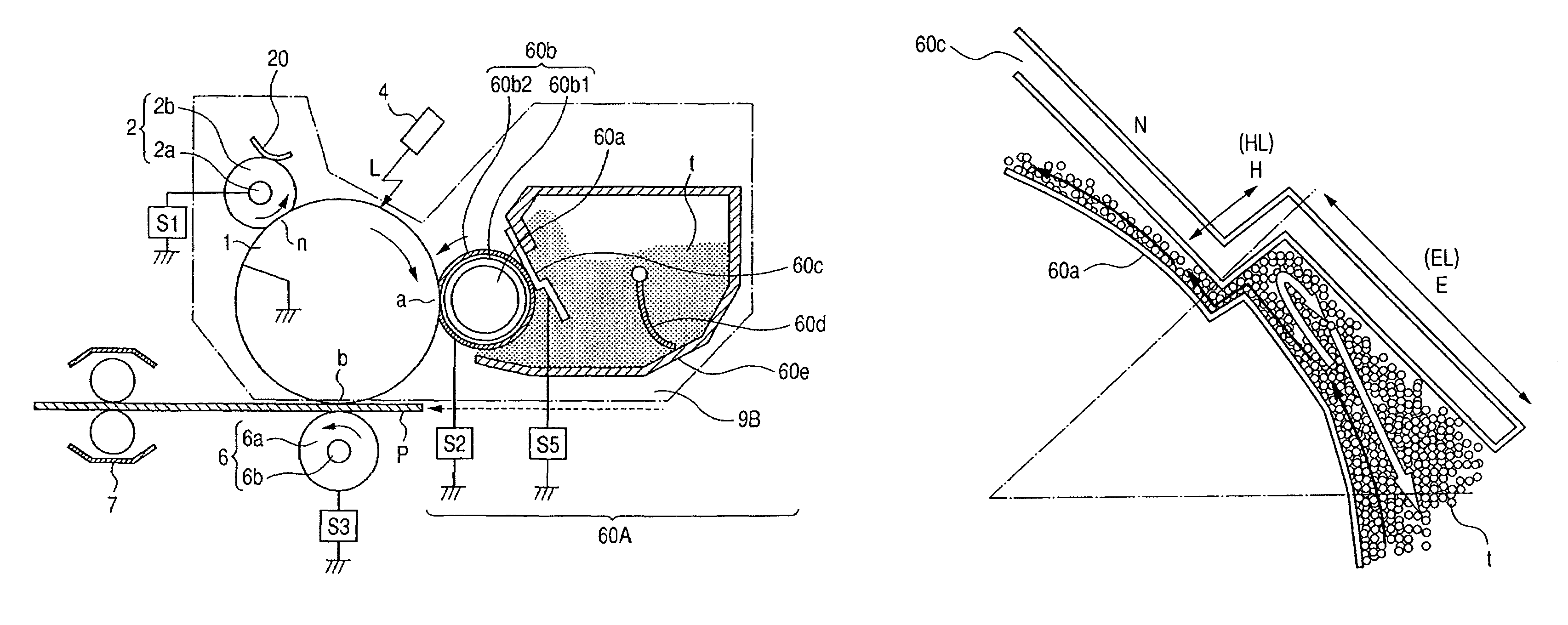
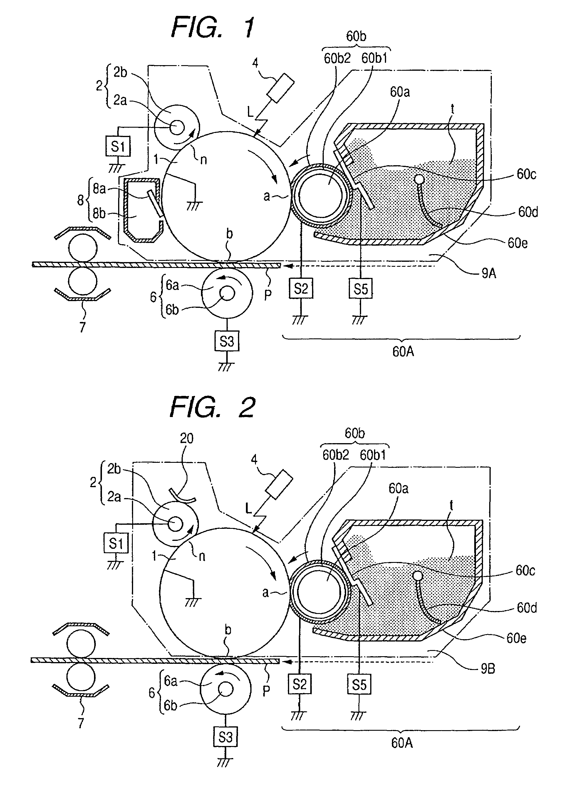
[0048]FIG. 2 schematically shows the construction of an image recording apparatus according to a second embodiment using the developing apparatus of the present invention. The image recording apparatus according to the present embodiment is a laser printer utilizing a transfer type electrophotographic process and a toner recycle process (cleaner-less system). The points of this example similar to those of the aforedescribed Example 2 of the image forming apparatus need not be described again, and only the different points thereof will hereinafter be described.

[0049]The most different point of the present embodiment is that the exclusive drum cleaner is disused and the untransferred residual toner is recycled. The toner is circulated so that the untransferred residual toner may not adversely affect the charging and other processes, and is collected in the developing device. Specifically, the following construction is changed relative to Example 1 of the ...

embodiment 2

Contact, Elastic Sleeve, Pole Position Regulating Portion, and Pole Position Separating Portion (Step Blade)

[0067]A developing apparatus according to the present embodiment basically corresponds to the developing apparatus 60A described in Embodiment 1, but differs in the abutting conditions of the regulating blade against the elastic sleeve from Embodiment 1.

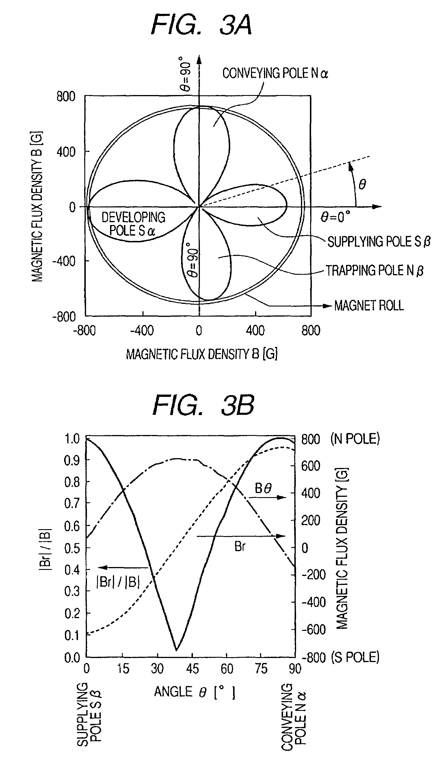
[0068]In the present embodiment, the abutting position of the regulating blade was set to θ=16°, pulling-out pressure 50 (N / m) and blade separating portion length 5 mm in FIGS. 3A and 3B.

[0069]The magnetic field of the regulating portion in the present embodiment was |Br| / |B|=0.80, and the magnetic field of the separating portion was |Br| / |B|=0.77.

[0070]Also, it will hereinafter be called pole position regulation (pole regulation) to set the abutting position of the regulating blade against the developing sleeve to a magnetic pole area (|Br| / |B|≧0.5) in which a vertical magnetic field is dominant as in the present embodiment.

embodiment 3

Contact, Elastic Sleeve, Inter-Pole Position Regulating Portion and Pole Position Separating Portion (Step Blade)

[0071]A developing apparatus according to the present embodiment basically corresponds to the developing apparatus 60A described in Embodiment 1, but the bias applied to the regulating blade is at potential equal to that applied to the developing sleeve.


PUM


Abstract

A developing apparatus having a rotatable developing sleeve having an elastic layer on the surface thereof for carrying a mono-component magnetic developer and urged against a photosensitive drum to develop an electrostatic image formed on the drum with the developer, a non-rotary magnet provided inside the sleeve for magnetically attracting the developer to the sleeve, and a blade having an abutting portion abutting against the sleeve in a counter direction for regulating the amount of the developer on the sleeve, a step portion spaced apart from the abutting portion, and a separating portion provided upstream of the step portion in the rotation direction of the sleeve, wherein the surface of the sleeve to which the separating portion is opposed includes a position satisfying |Br| / |B|≧0.5, where B(G): the magnitude of magnetic flux density formed on the surface of the sleeve, and Br(G): a component of the magnetic flux density in a direction perpendicular to the surface of the sleeve.

Description

BACKGROUND OF THE INVENTION[0001]1. Field of the Invention[0002]The invention relates to a developing apparatus for developing an electrostatic image formed on an image bearing member with a developer, and more particularly to a developing apparatus of a mono-component developing type having a developer carrying member urged against an image bearing member.[0003]Also, as the image bearing member, use can be made, for example, of an electrophotographic photosensitive member, an electrostatic recording dielectric member or the like, and the developing apparatus can be provided in a cartridge detachably mountable on an image recording apparatus (image forming apparatus) such as a copying machine or a printer, or an image forming apparatus main body.[0004]2. Description of the Related Art[0005]For example, in an electrophotographic image forming apparatus, (1) a nonmagnetic contact developing type and (2) a magnetic non-contact developing type are widely used as conventional mono-compon...

Claims


Application Information

Patent Timeline
Patent Type & Authority Patents(United States)
IPC IPC(8): G03G15/09
CPCG03G15/0921
Inventor OGAWA, KENYASHIMIZU, YASUSHIMORIYA, SHUJIHAGIWARA, KAZUNARIKICHIJIMA, NAOTOOKUDA, KOICHI
Owner CANON KK
Why Eureka
Try Eureka