Insect trap and method of use

a technology of insect traps and insects, applied in the field of insect traps, can solve the problems of affecting the removal of insects, affecting the availability of insects, and affecting the health of humans, so as to reduce the cost, increase the availability, and reduce the cos

Inactive Publication Date: 2008-06-03
GREENE URIL G +2
View PDF61 Cites 10 Cited by
  • Summary
  • Abstract
  • Description
  • Claims
  • Application Information

AI Technical Summary

Benefits of technology

[0017]It is yet another object of this invention to provide an insect trap which is inexpensive and simple to produce. Design features allowing this object to be achieved include the use of components made of readily available materials. Benefits associated with reaching this objective include reduced cost, and hence increased availability.

Problems solved by technology

Insects can be a major problem when uncontrolled.
Although numerous species of benevolent insects exist, others can present a health hazard to humans.
In addition, a large number of entrapment chambers were taught, thus rendering removal of the dead flies difficult.
While this mosquito killing apparatus may have been effective against mosquitoes or other insects coming into contact with the electroshock unit, it required a power supply, and suffered from the disadvantages of complexity, and its associated cost.
This required that insecticide be purchased, stocked, and periodically be replaced in the apparatus itself—with the associated labor, cost, and inconvenience.
If this task were to be neglected, the trap itself would become ineffectual.
Second, poisonous insecticide was required for the operation of this device.
When poison is used, the danger always exists that unintended animals or humans may come into contact with the poison, and deleterious health consequences ensue.

Method used


Image

  • Insect trap and method of use
  • Insect trap and method of use
  • Insect trap and method of use

Examples


Embodiment Construction

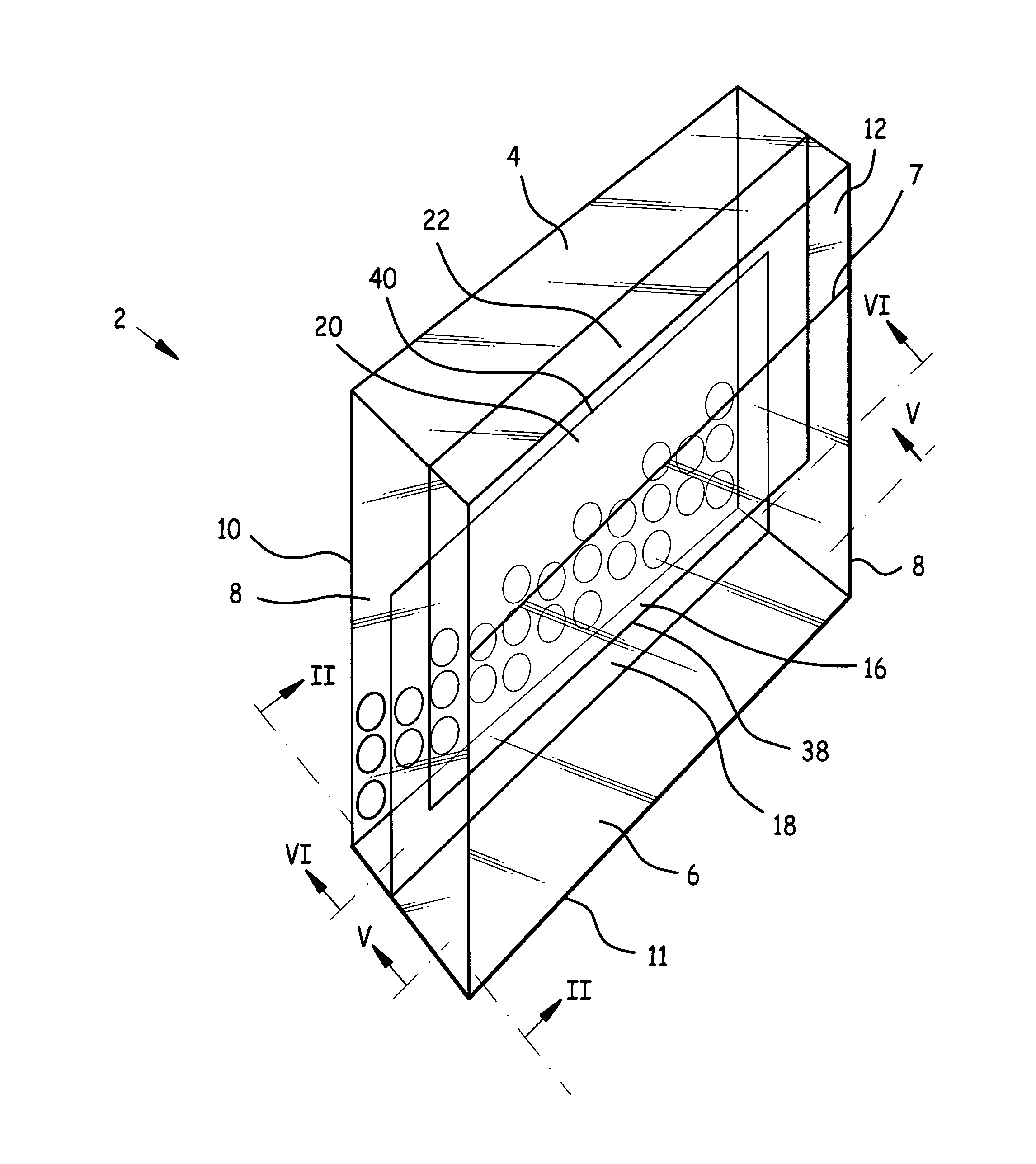
[0026]Referring now to FIG. 1 we observe a front quarter elevated isometric view of insect trap 2. Insect trap 2 comprises roof 4 rigidly attached to rear wall 10 and side walls 8, front wall 6 rigidly attached along edges of side walls 8 opposite rear wall 10, and floor 11 rigidly attached along edges of front wall 6, rear wall 10, and side walls 8 opposite roof 4.

[0027]First divider 16 depends from roof 4, and is attached at either side to a side wall 8. Second divider 20 as attached to floor 11, and at either side to a side wall 8.

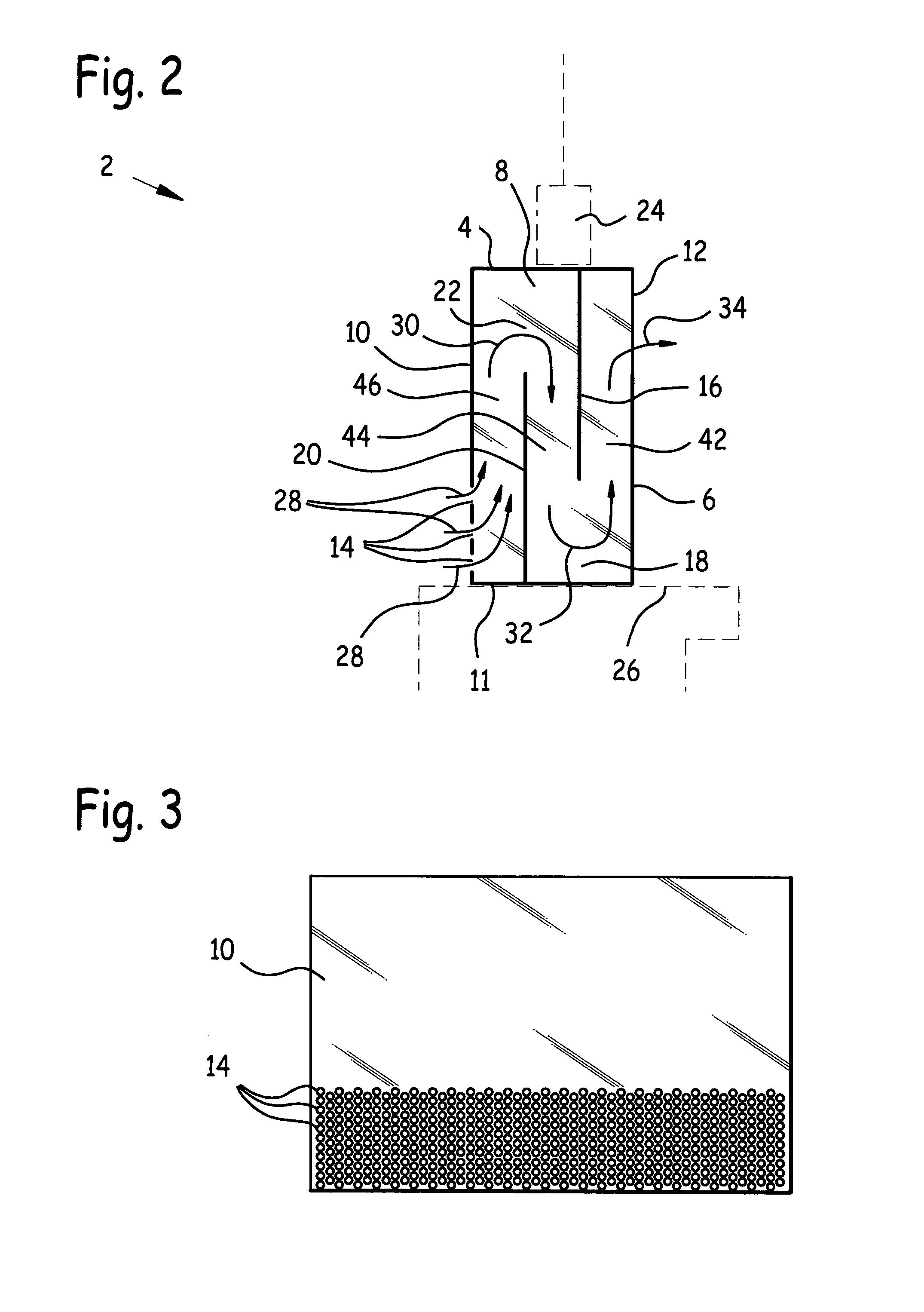
[0028]Front wall aperture 12 is disposed between front wall upper edge 7 and roof 4. First divider aperture 18 is disposed between first divider lower edge 38 and floor 11. Second divider aperture 22 is disposed between second divider upper edge 40 and roof 4. Rear wall apertures 14 are disposed in rear wall 10.

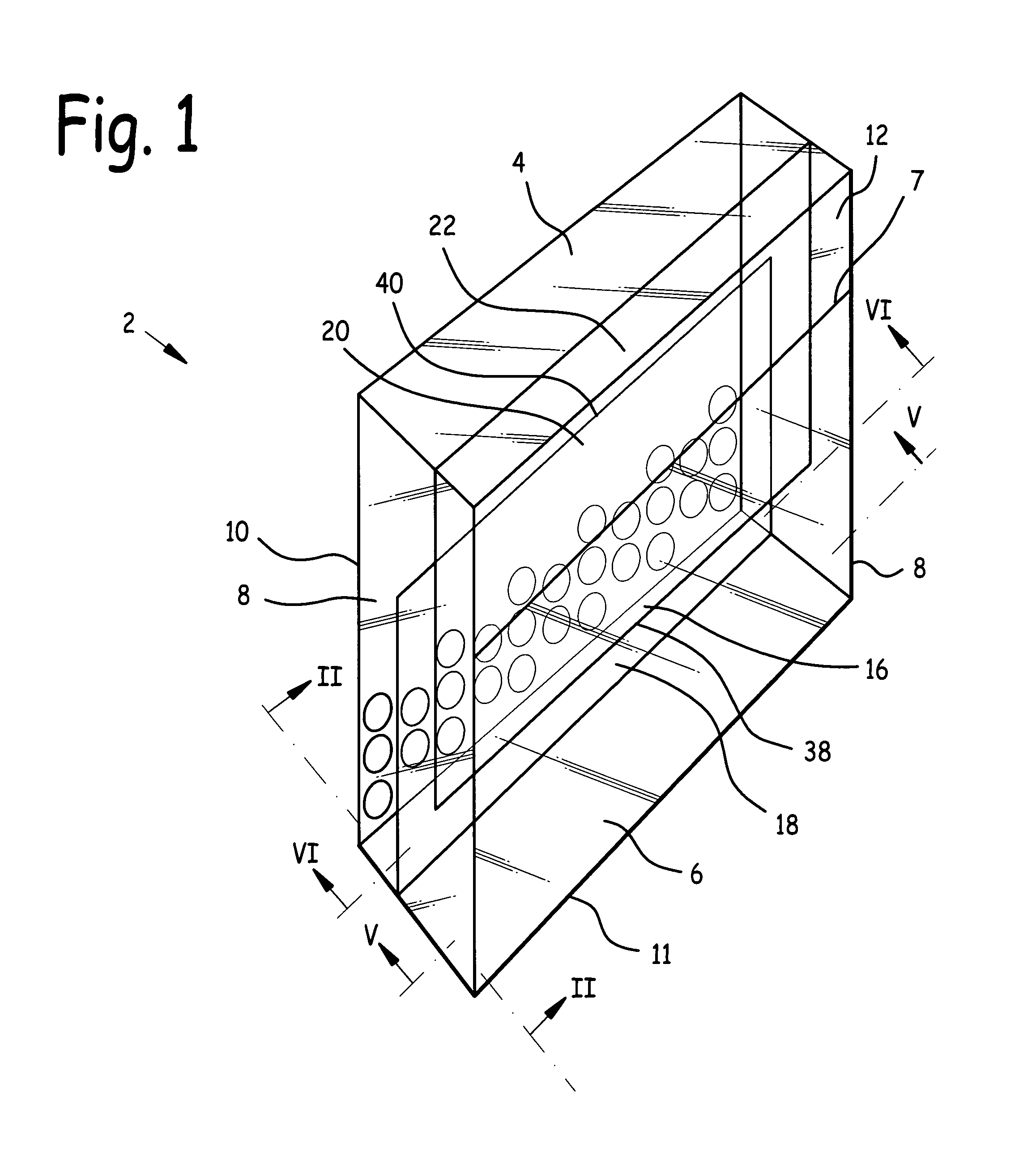
[0029]Referring now also to FIG. 2, a side cross-sectional view of insect trap 2 taken at section II-II of FIG. 1, outer chamber 42 is defined b...


PUM


Abstract

An insect trap and method of use. The insect trap has a roof, side walls, rear wall, front wall, and floor. The front wall has a front wall aperture, and the rear wall has at least one rear wall aperture. A plurality of dividers are disposed within the insect trap, with a divider aperture associated with each divider. The divider apertures alternate between being adjacent the floor and adjacent the roof in successive dividers. The method includes the steps of mounting an insect trap in a structure opening, allowing insect-enticing chemicals to waft from inside the structure opening to outside the structure opening through the insect trap, enticing the insect through a front wall aperture, divider apertures, and into an inner chamber adjacent the rear wall, and entrapping the insect within the inner chamber because the rear wall apertures are too small to admit passage to the insect.

Description

[0001]This application is a Continuation-In-Part of U.S. patent application Ser. No. 10 / 796,001 filed Mar. 10, 2004 now abandoned, and claims the benefit of the earlier filing date of that application.BACKGROUND OF THE INVENTION[0002]1. Field of the Invention[0003]This invention relates to pest control, and in particular to an insect trap and method of use.[0004]2. Background of the Invention[0005]Insects can be a major problem when uncontrolled. Although numerous species of benevolent insects exist, others can present a health hazard to humans. For example, mosquitoes spread malaria and yellow fever through their blood sucking feeding habits. Flies may carry disease, germs and infection by landing on food subsequently eaten by humans. Thus it would be desirable to reduce or eliminate these, and other harmful, types of insects from inside structures occupied by humans, and from the environs of same.[0006]It is known that insects such as mosquitoes are attracted by carbon dioxide exh...

Claims


Application Information

Patent Timeline
Patent Type & Authority Patents(United States)
IPC IPC(8): A01M1/24A01M1/02A01M1/10
CPCA01M1/023A01M1/10A01M1/106A01M1/24A01M2200/012Y02A50/30
Inventor GREENE, URIL GGREENE, ALAN THOMASGREENE, AISHA MIRETTE
Owner GREENE URIL G
Why Eureka
Try Eureka