Remotely operated water bottom based drilling system using cable for auxiliary operations

a remote-operated, water bottom-based technology, applied in the direction of underwater drilling, borehole/well accessories, core removal, etc., can solve the problems of limiting the water depth in which the riser is located, drilling using such risers is not well suited to drilling tasks, and the in-water weight of the riser is too large to achieve the effect of drilling

Inactive Publication Date: 2008-06-03
WILLIAMSON DEEP OCEAN ENG
View PDF9 Cites 68 Cited by
  • Summary
  • Abstract
  • Description
  • Claims
  • Application Information

AI Technical Summary

Benefits of technology

[0011]A method for drilling formations below the bottom of a body of water includes disposing a drilling system on the bottom of the body of water. The formations are drilled by rotating a first drill rod having a first core barrel latched therein and advancing the drill rod longitudinally. At a selected longitudinal position, an upper end of the first drill rod is opened and a cable having a latching device at an end thereof is lowered into the first drill rod. The winch is retracted to retrieve the first core barrel. The first core barrel is laterally displaced from the first drill rod. A s...

Problems solved by technology

Such drilling is a complicated and expensive operation, particularly in deep water where a drilling riser must be extended from the floating drilling structure to the sea floor to provide a return conduit for drilling fluid from the well as it is drilled.
In addition to cost, drilling using such riser is not well suited to drilling tasks requiring precise control of bit weight, stability (motion compensation) of the drill string and exact positioning of tools within the borehole.
The in-water weight of the riser limits ...

Method used


Image

  • Remotely operated water bottom based drilling system using cable for auxiliary operations
  • Remotely operated water bottom based drilling system using cable for auxiliary operations
  • Remotely operated water bottom based drilling system using cable for auxiliary operations

Examples


Embodiment Construction

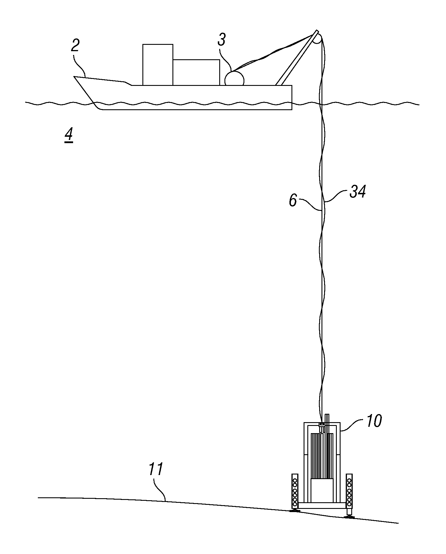
[0019]FIG. 1 shows a ship or vessel 2 having a winch 3 or similar spooling device thereon on the surface of a body of water 4 such as the ocean. The winch 3 can spool and unspool a deployment cable 6 and an umbilical cable 34 used to deploy a drilling system 10 on the bottom 11 of the body of water. The deployment cable 6 may nor may not be part of the same physical cable as the umbilical cable 34. A water bottom based drilling system 10 is deployed using the cable 6 and is caused to rest on the bottom 11 of the body of water. After drilling operations are completed, the system 10 may be retrieved and returned to the vessel 2.

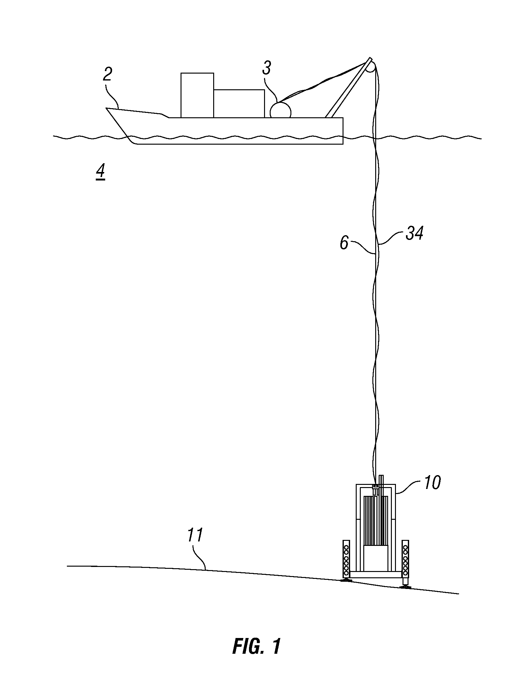
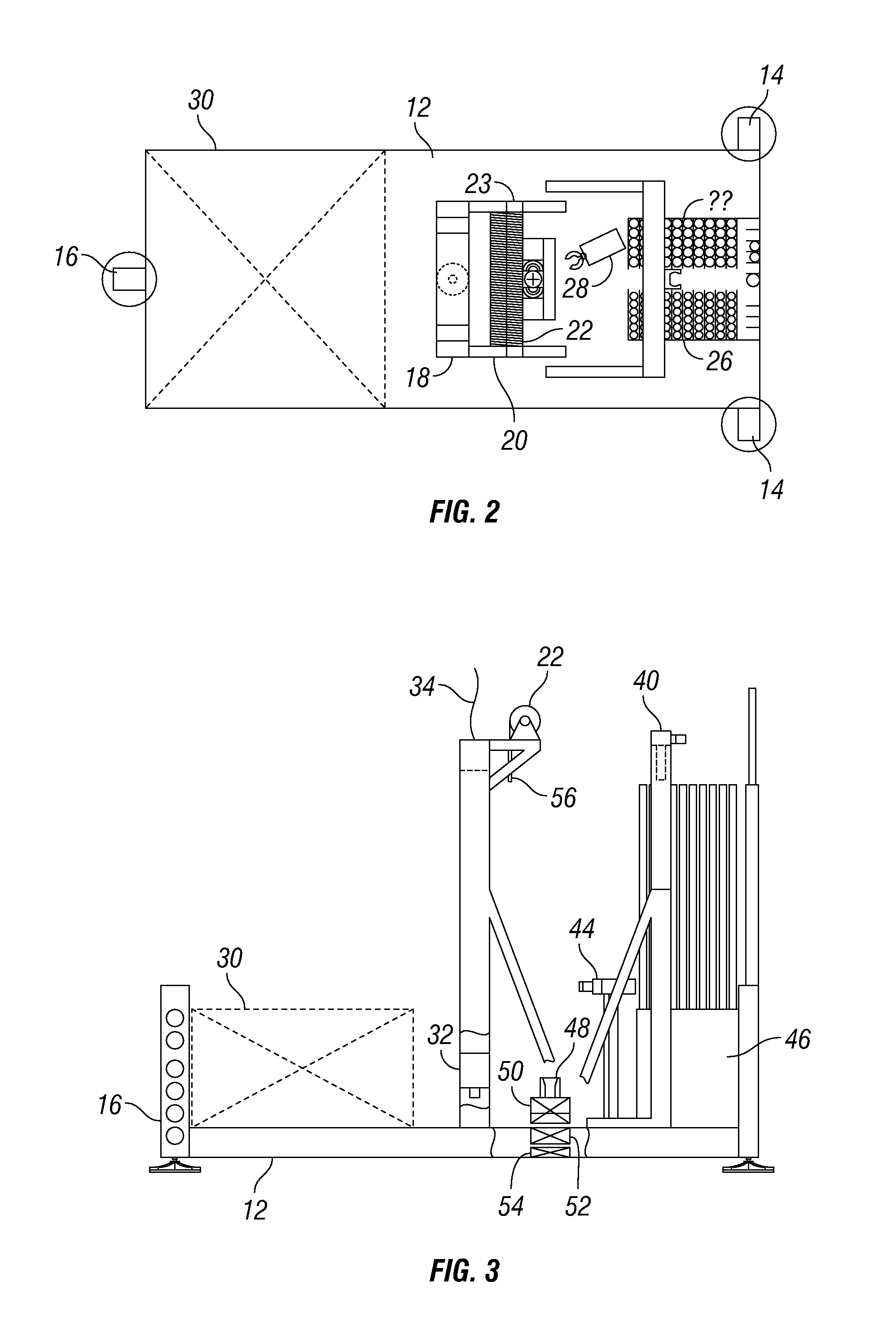
[0020]A plan view of an example drilling system is shown in FIG. 2. The system 10 is mounted on a frame 12 that provides support for the various components of the system 10. The frame 12 may have support legs 14 disposed on two corners to maintain the frame 12 in suitable orientation when the system 10 is disposed on the bottom of a body of water. An adjustable...


PUM


Abstract

A method for drilling formations below the bottom of a body of water includes disposing a drilling system on the bottom of the body of water. The formations are drilled by rotating a first drill rod having a first core barrel latched therein and advancing the drill rod longitudinally. At a selected longitudinal position, an upper end of the first drill rod is opened and a cable having a latching device at an end thereof is lowered into the first drill rod. The winch is retracted to retrieve the first core barrel. The first core barrel is laterally displaced from the first drill rod. A second core barrel is inserted into the first drill rod and latched therein. A second drill rod is affixed to the upper end of the first drill rod. Drilling the formation is then resumed by longitudinally advancing and rotating the first and second drill rods.

Description

CROSS-REFERENCE TO RELATED APPLICATIONS[0001]Not applicable.STATEMENT REGARDING FEDERALLY SPONSORED RESEARCH OR DEVELOPMENT[0002]Not applicable.BACKGROUND OF THE INVENTION[0003]1. Field of the Invention[0004]The invention relates generally to the field of drilling Earth formations below the bottom of a body of water. More specifically, the invention relates to remotely operated drilling devices that are positioned on the sea floor.[0005]2. Background Art[0006]Drilling through Earth formations located below the bottom of a body of water generally require the use of drilling equipment deployed from a barge or ship, and in the case of deep water sites, from a drillship or semisubmersible floating drilling platform. Such drilling is a complicated and expensive operation, particularly in deep water where a drilling riser must be extended from the floating drilling structure to the sea floor to provide a return conduit for drilling fluid from the well as it is drilled. In addition to cost...

Claims


Application Information

Patent Timeline
IPC IPC(8): E21B7/124
CPCE21B7/124E21B7/122
Inventor WILLIAMSON, MICHAEL EMCGINNIS, TIMOTHYTHATCHER, HERBERTROBINSON, LARRY
Owner WILLIAMSON DEEP OCEAN ENG
Why Eureka
Try Eureka