
Protective lifting system for outdoor use

a protective and outdoor technology, applied in the direction of gearing elements, belts/chains/gearrings, hoisting equipment, etc., can solve the problems of bringing certain risks into play, affecting the safety of users, so as to reduce the chance of lifting lines breaking and increase the usable life of lift lines

Inactive Publication Date: 2008-06-03
JOY COLIN +1
View PDF7 Cites 6 Cited by
  • Summary
  • Abstract
  • Description
  • Claims
  • Application Information

AI Technical Summary

Benefits of technology

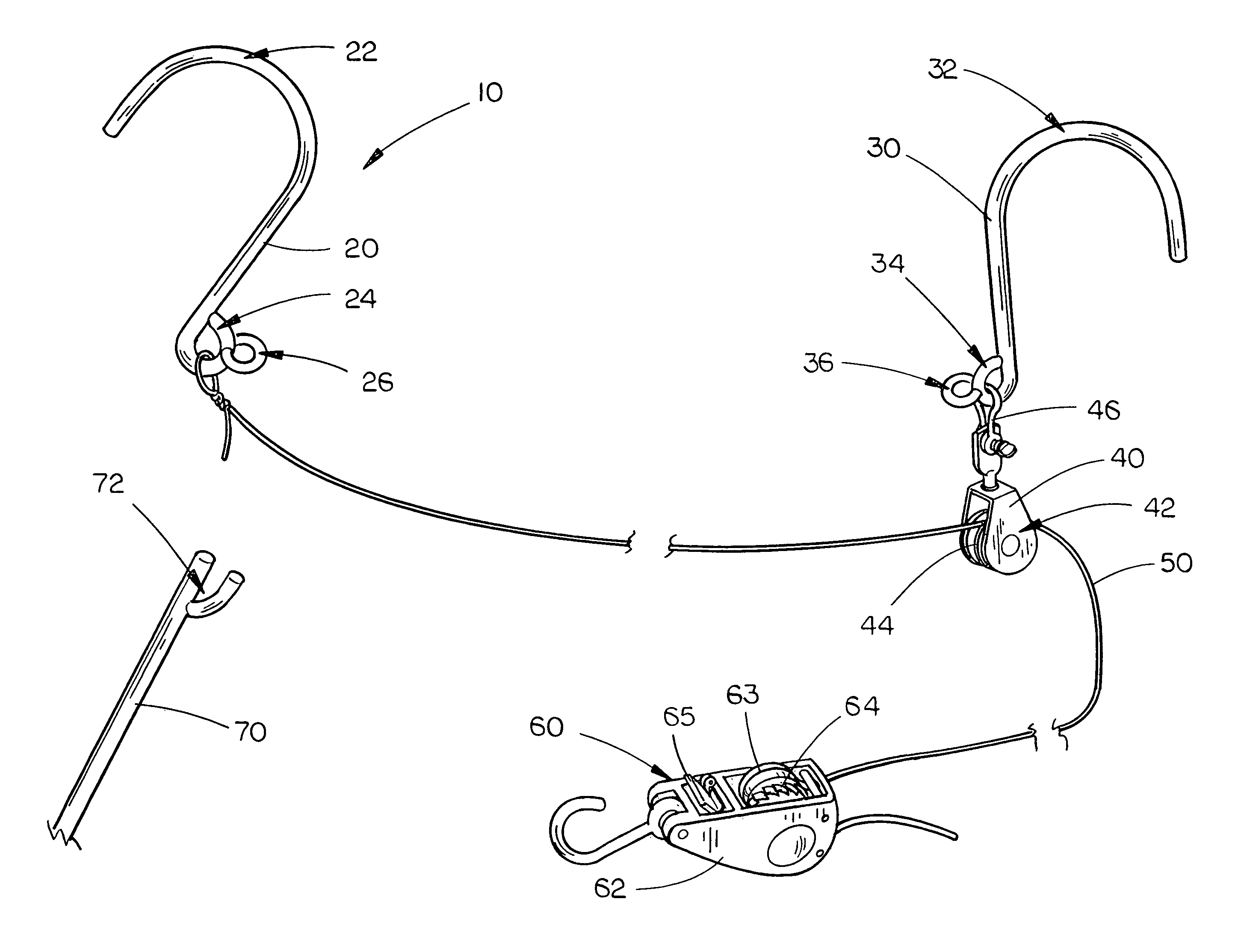
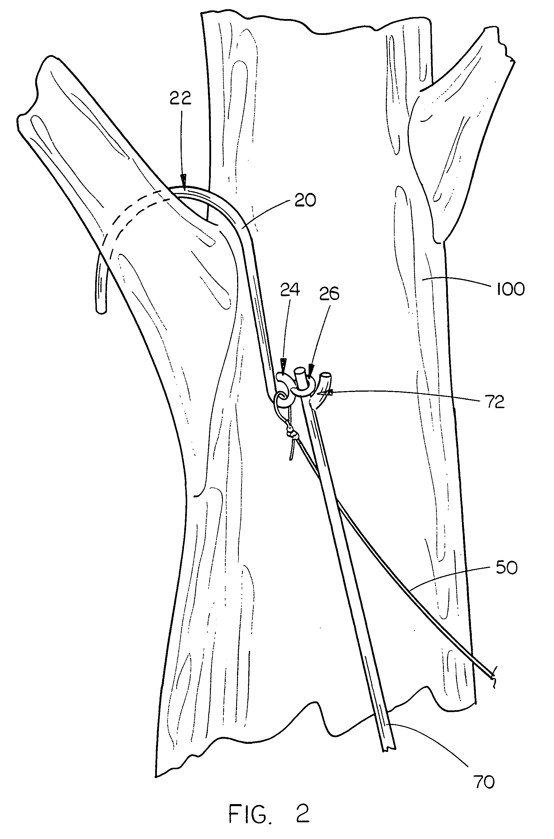
[0014]The protective lifting system for objects for suspending the objects in an elevated position of the present invention as thus described provides many improvements over those devices and systems found in the prior art. For example, because the present invention utilizes mounting hooks for securement of the system to the supporting objects, the mounting connection of the device to those supporting objects is far more secure than that obtainable by merely passing the supporting cable or cord over the supporting object. Also, because the first and second mounting hooks of the present invention include mounting bar connection eyelet rings which extend generally perpendicular to the shank section of the mounting hooks, it is a relatively simple matter to engage the mounting bar connection eyelet rings with a mounting bar including a topmost engagement section to lift the first and second mounting hooks into a support position engaging the supporting object instead of having to throw a rope or cord over the selected supporting object in a precise location to ensure that the supporting line is properly supported by the supporting object. Finally, because the present invention includes a pulley device mounted on the second mounting hook through which the lift line extends, wear and tear from frictional contact between the lift line and the supporting object is eliminated, thus greatly increasing the usable life span of the lift line and significantly decreasing the chances that the lift line will break at an inopportune time, such as during the lifting of or supporting of an object by the lift line. It is therefore seen that the present invention provides a substantial improvement over those devices and systems found in the prior art which attempt to perform similar functions.

Problems solved by technology

While these visits are, for the most part, exciting and enjoyable, visits and stays in wilderness areas also bring certain risks into play which are not encountered in ordinary daily life.
For example, one of the largest and potentially most dangerous animals frequently encountered in wilderness areas is the bear, particularly black bears, and these intelligent and curious animals spend a great deal of time exploring for food.
Most commonly, hikers and campers store their food, toiletries, and garbage in either bear resistant containers or in what are commonly referred to as “food hangs.” While hikers and campers would ideally carry bear resistant containers for their food, toiletries, and garbage with them, most bear resistant containers are bulky and heavy and are difficult to transport during hiking and camping.
It is easy to see, however, how the ordinary method of preparing and completing a food hang is a cumbersome and time-consuming process.
For example, one must extend the rope over two selected trees, with all the attendant difficulties inherent in performing such an action, due to the numerous branches, twigs and leaves which are in the way when the rope is being thrown over a particular selected branch.
Also, one must ensure that the branch selected is of sufficient strength to support the hanging bag, and because of the method by which the rope is thrown over the branch, it may be difficult to select and accurately throw the rope over an appropriate branch unless one is quite skilled in the art of rope throwing.

Method used


Image

  • Protective lifting system for outdoor use
  • Protective lifting system for outdoor use
  • Protective lifting system for outdoor use

Examples


Embodiment Construction

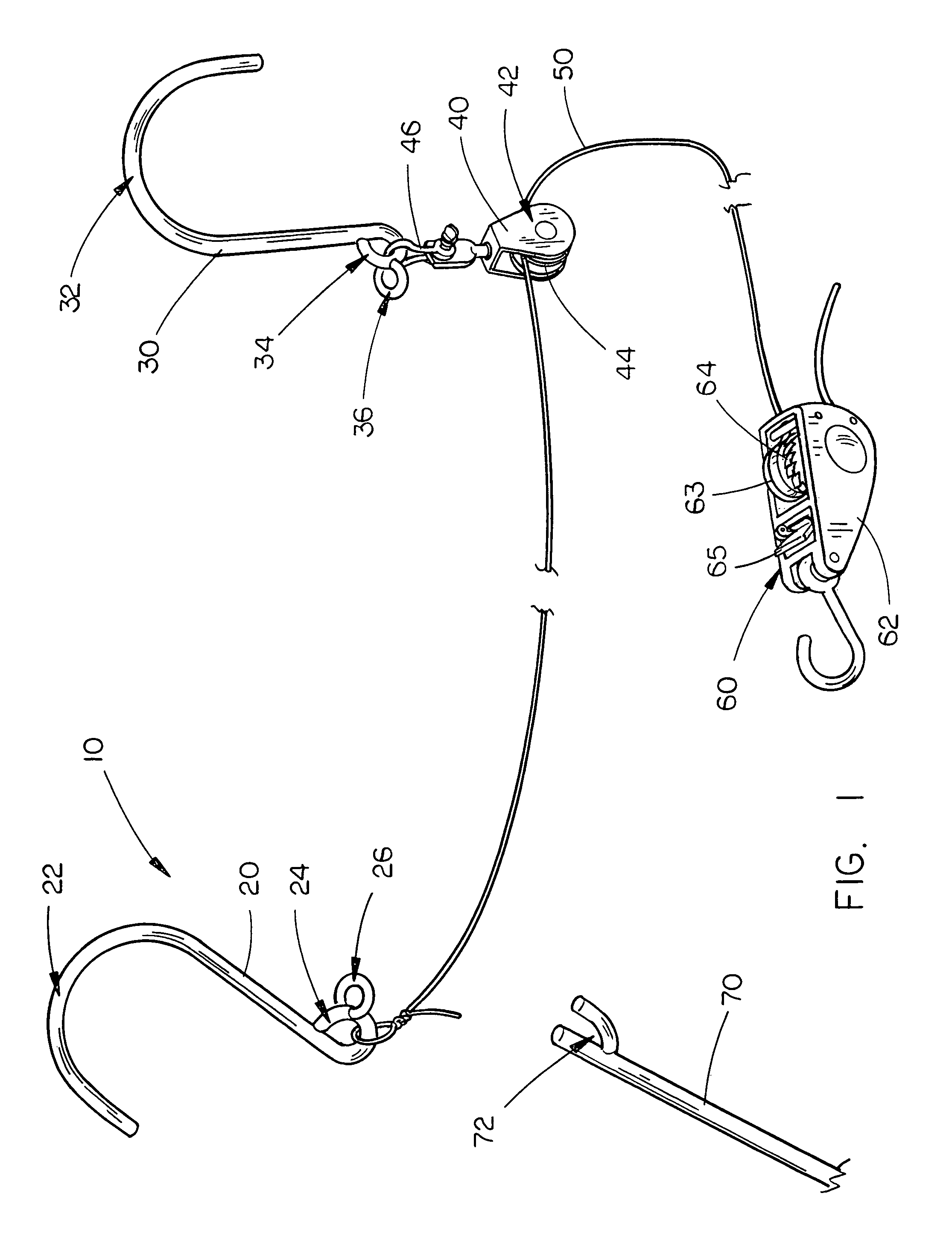
[0018]The protective lifting system 10 for objects for suspending the objects in an elevated position is shown best in FIGS. 1-3 as including a first mounting hook 20 which includes an arcuate hook section 22, a line connection eyelet ring 24 mounted on the shank end of the mounting hook 20 and a mounting bar connection eyelet ring 26 which is mounted on the line connection eyelet ring 24. In the preferred embodiment, the mounting bar connection eyelet ring 26 would extend perpendicularly to the line connection eyelet ring 24 and hence perpendicular to the hook section 22 of first mounting hook 20. This makes it easier for the mounting bar connection eyelet ring 26 to be engaged by a mounting bar 70 as will be described later in this disclosure.

[0019]A second mounting hook 30 is also included in the present invention, the second mounting hook 30 including a hook section 32 generally identical to first mounting hook 20, a pulley connection eyelet ring 34 generally identical to line c...


PUM


Abstract

A protective lifting system includes first and second mounting hooks each having, respectively, a line and pulley connection eyelet ring mounted thereon and a mounting bar connection eyelet ring mounted thereon which extends generally perpendicular to the shank section of the mounting hook, a pulley device mounted on the second mounting hook, a lift line having a first end connected to the first mounting hook and a second end which extends through the pulley device, a mounting bar operative to engage the mounting bar connection eyelet ring on the first and second mounting hooks to lift the hooks into an elevated supported position, the lift line being operative to lift an object to a safe elevated position by drawing the second end of the lift line through and away from the pulley device thereby decreasing the length of the lift line extending between the first and second mounting hooks.

Description

BACKGROUND OF THE INVENTION[0001]1. Technical Field[0002]The present invention is directed to food and backpack hanging systems for use by campers and other outdoorsmen and, more particularly, to a protective lifting system for objects for suspending the objects in an elevated position which includes first and second mounting hooks each having, respectively, a line and pulley connection eyelet ring mounted thereon and a mounting bar connection eyelet ring mounted thereon which extends generally perpendicular to the shank section of the mounting hook, a pulley device mounted on the second mounting hook, a lift line having a first end connected to the first mounting hook and a second end which extends through the pulley device, a mounting bar having a topmost engagement section which is operative to engage the mounting bar connection eyelet ring on the first and second mounting hooks to lift the hooks into an elevated position for engagement on a supporting object with the lift line e...

Claims


Application Information

Patent Timeline
Patent Type & Authority Patents(United States)
IPC IPC(8): B66D1/00
CPCB66D3/02
Inventor JOY, COLINFALLER, RICK
Owner JOY COLIN
Learn More