Foot pedal for drum

a foot pedal and drum technology, applied in the field of foot pedals for drums, can solve the problems of troublesome adjustment operation, limited adjustment range of setting angle , difficulty in clamping the hoop with a large holding or binding force, etc., to achieve the effect of large external force, large external force, and extended contact area

Inactive Publication Date: 2008-06-03
YAMAHA CORP
View PDF15 Cites 12 Cited by
  • Summary
  • Abstract
  • Description
  • Claims
  • Application Information

AI Technical Summary

Benefits of technology

[0016]The present invention was devised in order to address the above-described problems, and has as an object of providing a foot pedal for a drum that can clamp the hoop reliably regardless of the board thickness of the hoop, that improves operability and a handling along with providing a good appearance, and that extends a freedom of a setting angle of the foot board.
[0021]In accordance with the present invention, the hoop pushing unit is provided and its height can be adjusted, therefore, it is easy to adjust the height of the hoop pushing unit and it improves operability and handling of the foot pedal. There is no possibility that a footboard hits the hoop pushing unit, therefore, it is possible to apply the setting angle of the foot pedal smaller and to extend the range of the setting angle.
[0022]Moreover, the hoop clamp operation unit is provided such that it is not protruding at the right or left side of the foot board, therefore, its appearance is not harmed and space for storing can be smaller.
[0023]In accordance with the present invention, by applying the clamp holding unit, the hoop clamp is rotated upon clamping, the setting angle is not changed because of the board thickness of the hoop and it is possible to improve the freedom of changing of the setting angle of the foot board.
[0025]In accordance with an aspect of the present invention, the hoop clamp is provided with rotatability in backward and forward directions around a rotation shaft which is a fulcrum, therefore, it is possible to provide a large external force at a front edge portion by applying a leverage. Moreover, the clamp holding unit is constituted from the cam provided under a rear edge portion of the hoop clamp with rotatability and the clamp lever that rotates the cam, therefore, a larger external force can be provided on the hoop clamp.
[0026]In accordance with still another aspect of the present invention, the hoop holding and binding lever is further included, therefore, compared to a hoop pushing means constructed from a bolt, it is possible to extend a contact area and to clamp the hoop stably and reliably.

Problems solved by technology

In accordance with the conventional hoop pushing apparatus 4 above, the adjuster bolt 14 is attached at a rear edge side of the hoop clamp 13, therefore, in a case such that a setting angle α is small, when the footboard 5 is stepped on, there is a possibility that the footboard 5 may hit the adjuster bolt 14 or the hoop clamp 13, and therefore, there is a problem in that an adjustment range of the setting angle α is limited.
Moreover, the adjuster bolt 14 is set at a position under the footboard 5, therefore, a hand should be inserted under the footboard 5 and the adjuster bolt 14 should be rotated (screwed, or wrenched) upon adjusting it, that is, there is a problem in that an adjusting operation is troublesome.
However, in accordance with such a structure, the hoop should be clamped by using a clamping force in order to clamp the hoop, therefore, it is difficult to clamp the hoop with a large holding or binding force, and therefore, there is a problem in that the hoop is easily disengaged from the two members in the shape like an alligator's mouth because of vibrations and the like upon playing.
However, in a case of providing the hoop clamp operation unit protruding at the right or left side of the foot board, a larger setting space is needed for the foot pedal for the drum upon using, therefore, there is a problem in that settings of other drums or stands for music instruments are limited.
In a case of providing the hoop clamp operation unit protruding at the right or left side of the foot board, there are problems such that it has a poor appearance and a larger space for storing is needed.

Method used


Image

  • Foot pedal for drum
  • Foot pedal for drum
  • Foot pedal for drum

Examples


Embodiment Construction

[0034]Hereafter, the present invention is explained in detail based on an embodiment referring to figures.

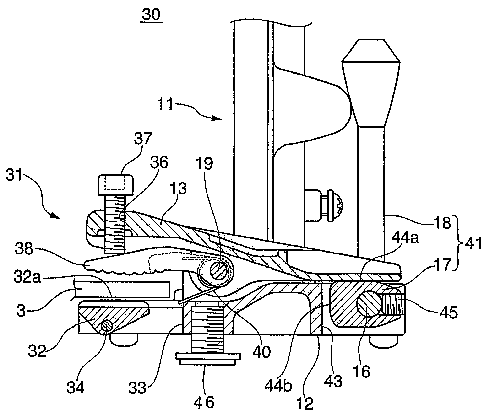
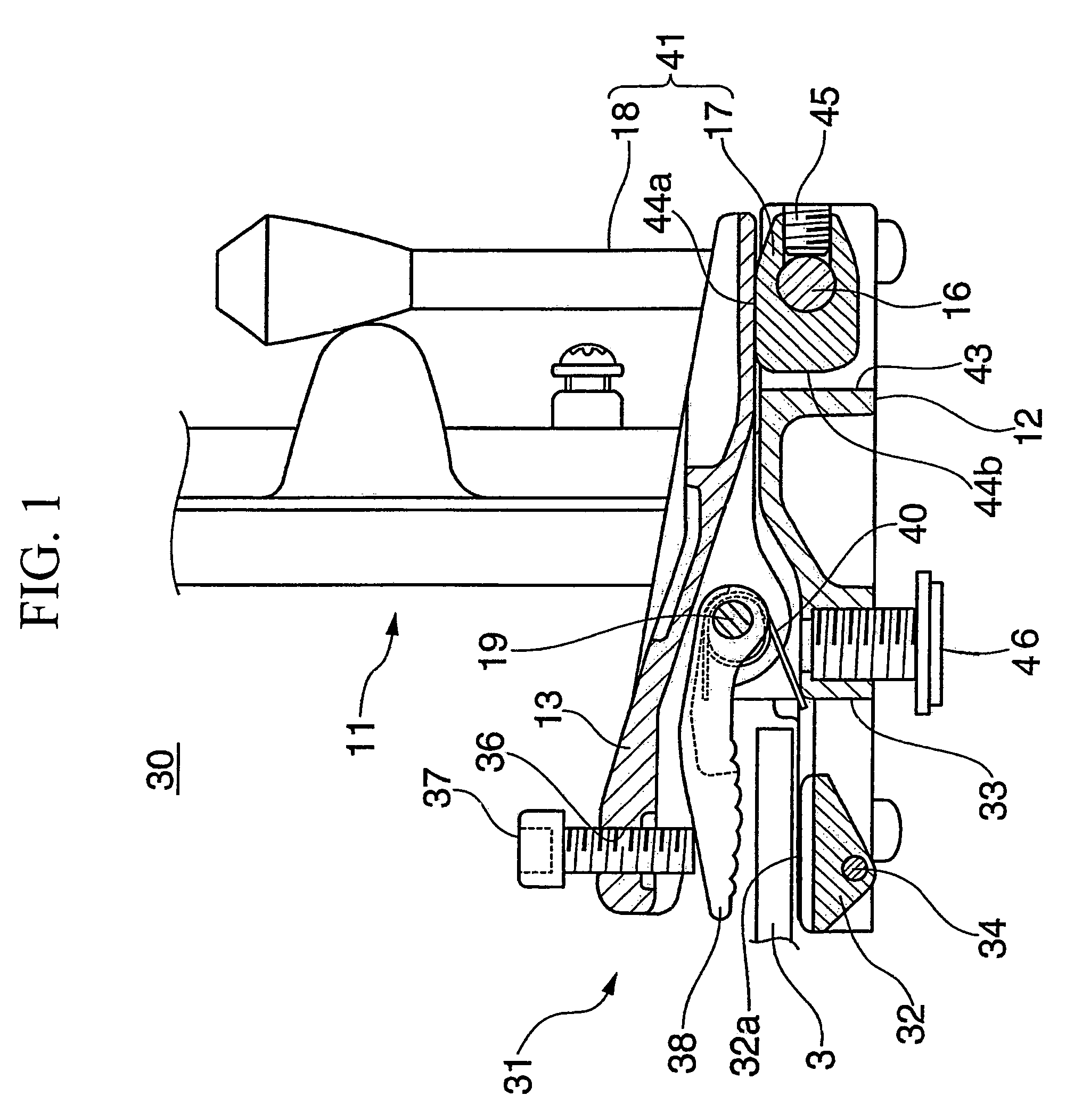
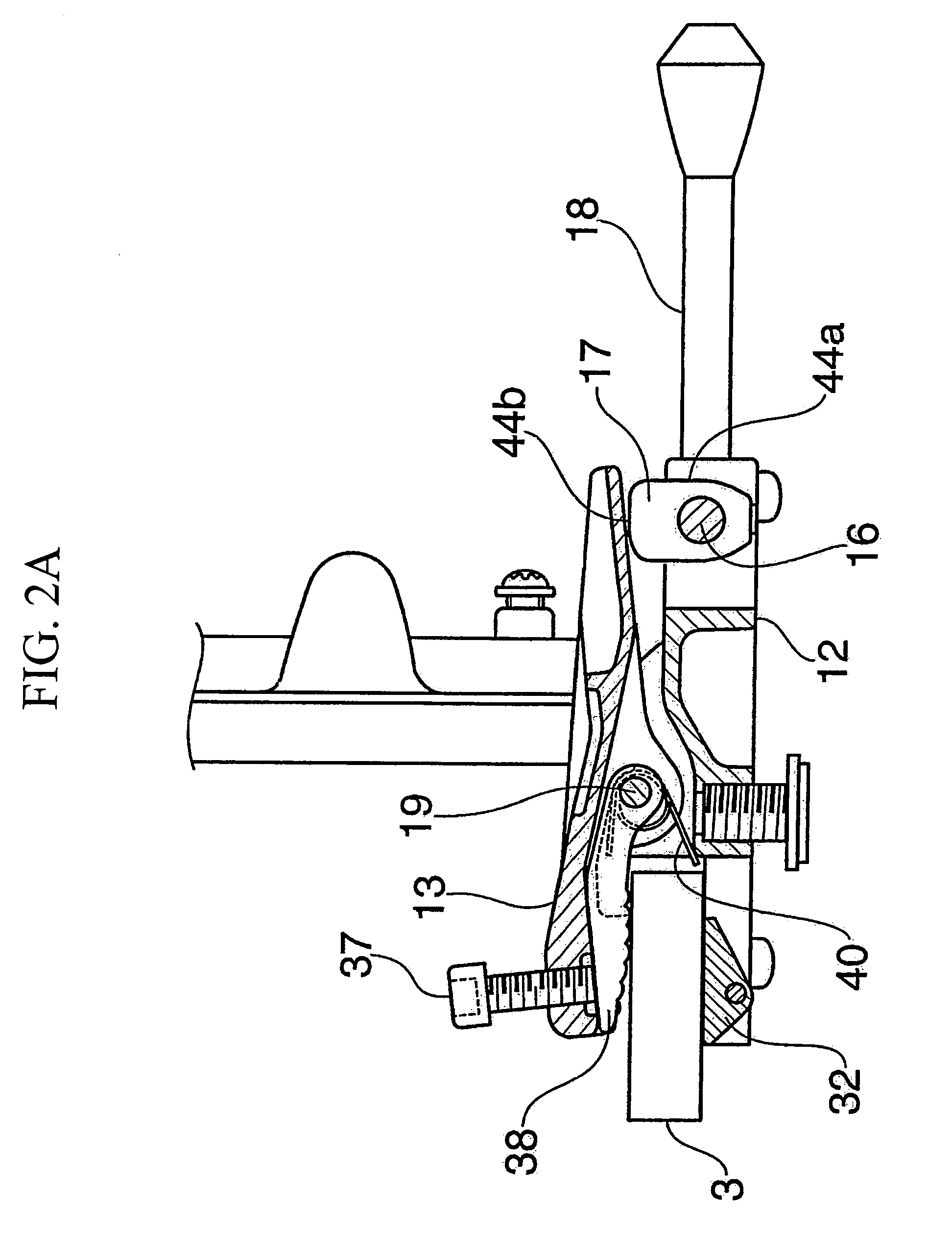
[0035]FIG. 1 shows a principal part of a foot pedal for a drum of the present invention when not clamped, and FIGS. 2A and 2B show states upon clamping hoops with a large board thickness and a small board thickness. It should be noted that the same portions and / or parts are referred by using the same symbols (reference numerals) for a foot pedal of the prior art shown in FIGS. 3 and 4.

[0036]In FIGS. 1 and 2, a foot pedal 30 of a drum of the present invention, as with the foot pedal for the drum of the prior art shown in FIG. 3, includes a pedal frame 11 in a square shape upon viewing from the front, a footboard 5 stepped on by a player with his / her foot, a beater 9 (see FIG. 3) which beats a drum head 10 and the like. However, there is a difference in a hoop clamping apparatus 31 provided at a supporting bar base 12 of the pedal frame 11 and clamping a hoop 3 of a bass drum 2, f...


PUM


Abstract

The present invention provides a foot pedal for a drum that can clamp a hoop regardless of a board thickness of a hoop, improves an operability, handling and moreover, appearance, and increases a freedom of a setting the angle of a foot board. A pedal frame provides a hoop pushing apparatus that clamps a drum hoop. The hoop pushing apparatus includes: a hoop clamp with rotatability; a bolt that is provided at a front edge portion of the hoop clamp, piercing the hoop clamp, and can be adjusted in height; a hoop holding and binding lever that is provided at a bottom side of the hoop clamp with rotability; and a clamp holding mechanism that rotates and holds the hoop clamp at a certain height. The hoop pushing apparatus, upon clamping, holds and binds the hoop with a hoop receiving member and the hoop holding and binding lever.

Description

BACKGROUND OF THE INVENTION[0001]1. Field of the Invention[0002]The present invention relates to a foot pedal for a drum for beating a drumhead on a bass drum by using the foot.[0003]Priority is claimed on Japanese Patent Application No. 2005-167913, filed Jun. 8, 2005, the content of which is incorporated herein by reference.[0004]2. Description of the Related Art[0005]This kind of foot pedal used for playing the bass drums has a hoop clamping apparatus for clamping a hoop (a frame for clamping) (for example, see Japanese Patent Application, First Publication No. H11-184461, Japanese Patent Application, First Publication No. H05-73032 and Japanese Patent Application, First Publication No. H08-248949).[0006]FIG. 3 and FIG. 4A-C show an example of a foot pedal for a drum in a prior art. A foot pedal 1 of the drum has a hoop clamping apparatus 4 clamping a hoop (clamping frame) 3 of a drum 2, and upon stepping on a footboard 5, a leg-power transmission member 6 is pulled down and a ro...

Claims


Application Information

Patent Timeline
Patent Type & Authority Patents(United States)
IPC IPC(8): G10D13/02
CPCG10D13/006G10D13/11
Inventor SHIGENAGA, FUMIHIRO
Owner YAMAHA CORP
Why Eureka
Try Eureka