White light emitting diode using phosphor excitation

a light-emitting diode and white light-emitting technology, which is applied in the direction of discharge tube/lamp details, luminescnet screen, discharge tube/lamp details, etc., can solve the problem of low color rendering index, difficulty in controlling the proportions of the participation of blue and yellow lights, and white lights usually have a non-uniform light color. achieve the effect of increasing the lifetime of white leds

Inactive Publication Date: 2008-06-03
CHEN LUNG CHIEN +2
View PDF8 Cites 121 Cited by
  • Summary
  • Abstract
  • Description
  • Claims
  • Application Information

AI Technical Summary

Benefits of technology

[0009]A main objective of the present invention is to provide a white LED, which separates the excitable entities (i.e. phosphors) from the light source (i.e. a blue or a UV LED die) so that the phosphors do not directly contact with the LED die to avoid the heat deterioration problem, thereby increasing the lifetime of the white LED of the present invention.
[0010]Another main objective of the present invention is to provide a white LED, which utilizes a simple reflective structure through which the phosphors could be excited more than once by the blue lights or UV lights emitted from the blue or UV LED die, thereby increasing their reaction. As a result, the white light uniformity, color temperature, and color rendering problems of the LED could be effectively resolved.
[0011]To achieve the foregoing objectives, the present invention provides a reflective mirror arranged on the light emitting path of the blue or the UV LED die at an appropriate inclined angle, which could reflect and redirect the blue lights or UV lights to be emitted out from an emitting plane of the LED. The phosphors are coated on the reflective mirror, the emitting plane of the LED, or both so as to achieve the separation of the phosphors and the LED die. In addition, if the phosphors are coated on both the reflective mirror and the emitting plane, the phosphor coated on the reflective mirror is firstly excited by the blue lights or UV lights emitted by the die to generate white lights, and the white lights together with the remaining blue lights or UV lights whose energy is not yet consumed are reflected by the reflective mirror toward the emitting plane. These remaining blue lights or UV lights get a second chance to react with the phosphors coated on the emitting plane. As a result, a uniform light color, a low color temperature, and a good color rendering index could be achieved.

Problems solved by technology

However, with this technique, it is difficult to control the proportions of the participated blue and yellow lights and, as a result; the generated white lights usually have a non-uniform light color, too high a color temperature, and too low a color rendering index.
However, this technique still suffers the difficultly in controlling the proportions of RGB phosphors, although the UV lights themselves do not participate in forming the white lights.
As a result, the color uniformity, color temperature, and color rendering problems are not satisfactorily resolved.
The foregoing techniques have another disadvantage.
The phosphors coated on or filled around the LED die would be deteriorated due to the heat generated from the LED die itself, which would further compromise the performances of the LED including its color, brightness, and lifetime.
However, the above-mentioned techniques could still not solve the phosphors' deterioration problem from direct contact with the LED die.
Furthermore, the arrangement of the filter or the reflectors would also add to the process complexity, resulting in high manufacturing cost and low yield.
However, this technique is designed for a lamp including many blue LEDs, but not for an individual LED.

Method used


Image

  • White light emitting diode using phosphor excitation
  • White light emitting diode using phosphor excitation
  • White light emitting diode using phosphor excitation

Examples


first embodiment

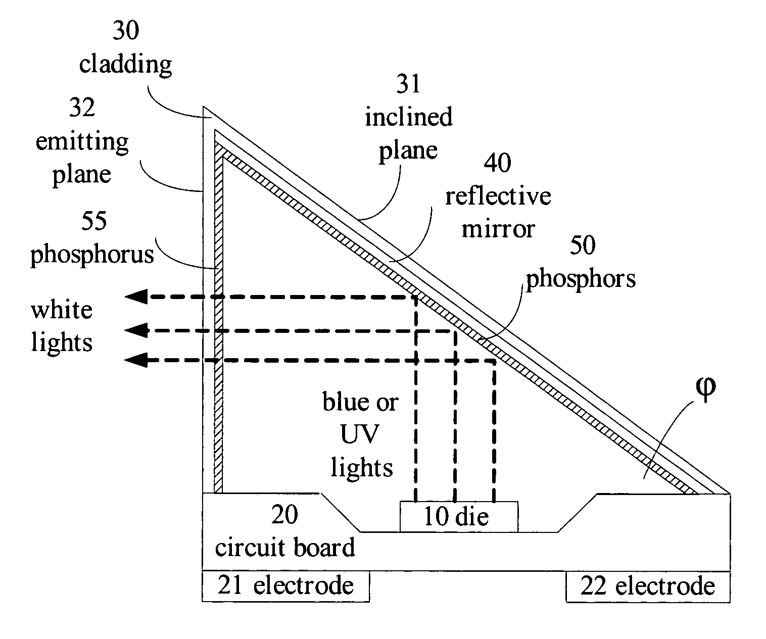
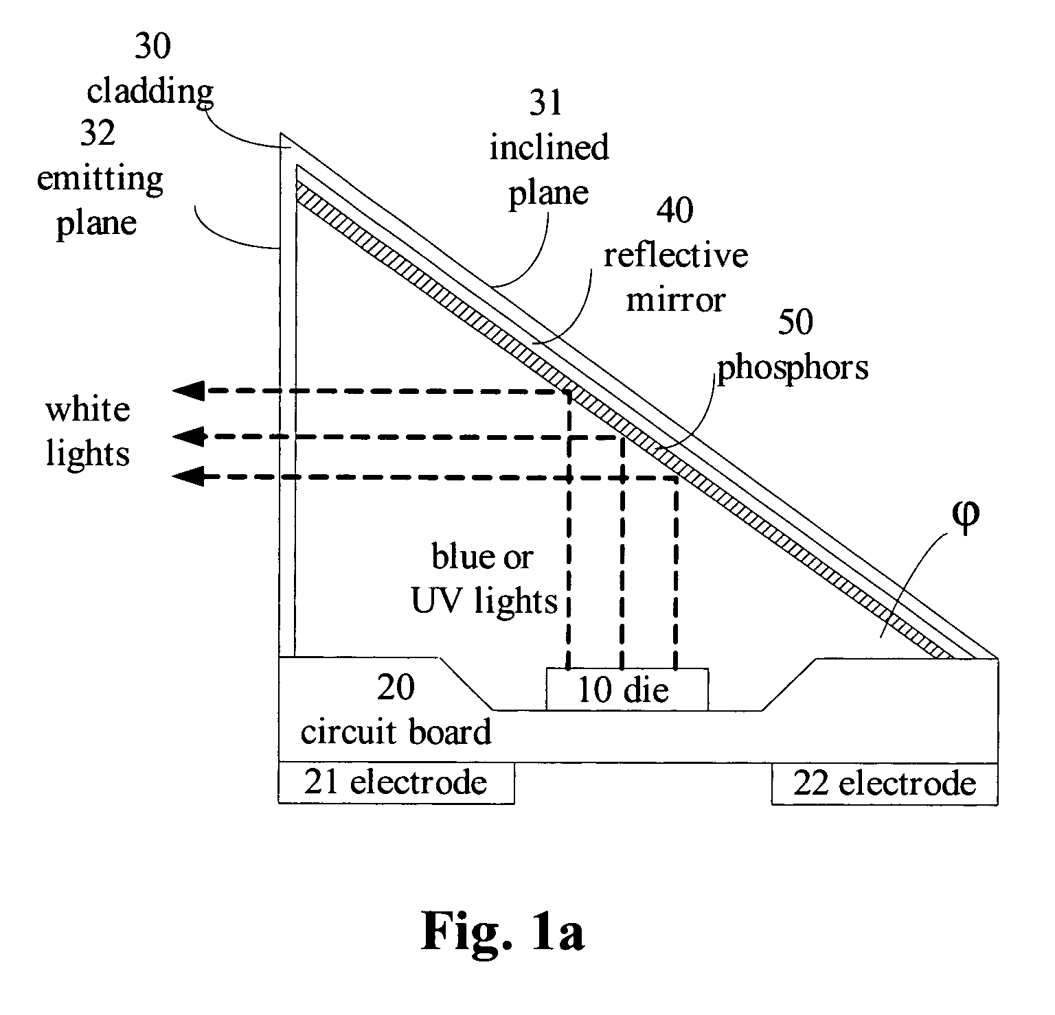
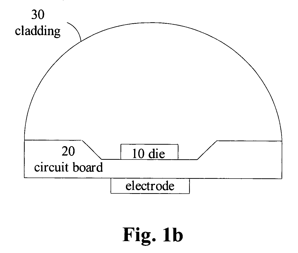
[0017]FIGS. 1a and 1b show a cross sectional side view, and a front view of the white LED according to the present invention, respectively. As shown in FIG. 1a and FIG. 1b, a conventional blue or UV LED die 10 is arranged on a circuit board 20 having a positive electrode 21 and a negative electrode 22. The LED die 10 is driven to emit blue lights or UV lights when an external voltage is applied onto the positive electrode 21 and the negative electrode 22.

[0018]A conventional LED is usually encapsulated in a transparent, cylindrical bell cladding made of epoxy to protect the LED die 10 and the circuit board 20 therein. Meanwhile, the bell cladding also provides light convergence similar to a convex lens. Instead of using a bell cladding, a cylindrical cladding 30 having an inclined plane 31 on the top, as if it is obtained from cutting a right cylinder in half at an inclined angle, is used in this embodiment. The included angle φ between the inclined plane 31 and the circuit board 20...

second embodiment

[0024]In this embodiment, a simple reflective structure in which the phosphors and the LED die are separately arranged, thereby preventing the phosphors from heat deterioration and avoiding the problem of reduced lifetime of the LED. Based on the same concept, in another embodiment, the phosphors are coated on the inner surface of the emitting plane 32, but not on the reflective mirror 40, as shown in FIG. 1c. Similarly, the phosphors 55 coated on the inner surface of the emitting plane 32 would produce complimentary lights when excited to the radiation of the LED die 10. In the second embodiment, the blue lights or UV lights emitted by the LED die 10 proceeds toward the emitting plane 32 after being reflected by the reflective mirror 40. The phosphor 55 is then excited by the reflected blue lights or UV lights, and the produced lights are mixed with the blue lights or UV lights to form white lights. The generated white lights then emits through the emitting plane 32.

[0025]In the fo...

third embodiment

[0026]In summary, a simple reflective structure is adopted in the third embodiment so that the blue light or the UV light emitted by the LED die could react with the phosphors twice. As a result, the generated white lights are more uniform, and the problems of the color temperature and the color rendering could be avoided. On the other hand, the present invention can provide two or more reflective mirrors, part of or all of which are coated with phosphors, and the phosphors can be excited twice or more times by the reflections of these reflective mirrors.


PUM


Abstract

A white light emitting diode (LED) is provided, which includes a reflective mirror arranged on the light emitting path of a blue or an ultra violet LED die at an appropriate angle. Phosphors are coated on the reflective mirror, the emitting plane of the LED, or both so that the phosphors are excited by the blue or UV lights emitted by the LED die to produce white lights. The present invention provides a white LED having a long lifetime and a uniform light color by separating the phosphors from the LED die, and by allowing the lights emitted from the LED die to undergo several excitations with the phosphors.

Description

BACKGROUND OF THE INVENTION[0001]1. Field of the Invention[0002]The invention generally relates to white light emitting diodes, and more particularly to a white light emitting diode using phosphor excitation with the phosphor separated from the die.[0003]2. The Prior Arts[0004]One of the more common and mature white light emitting diode (LED) technologies is to coat or fill a yellow phosphor on or around a blue LED die. The yellow phosphor is excited by radiation from the blue LED and emits yellow lights. The blue lights emitted by the LED are then mixed with the complimentary yellow lights from the phosphor to generate two-wavelength white lights. However, with this technique, it is difficult to control the proportions of the participated blue and yellow lights and, as a result; the generated white lights usually have a non-uniform light color, too high a color temperature, and too low a color rendering index.[0005]In another similar technology, red, green, and blue (RGB) phosphors...

Claims


Application Information

Patent Timeline
Patent Type & Authority Patents(United States)
IPC IPC(8): H01J1/62F21V9/00
CPCH01L33/507H01L33/60H01L33/486H01L2924/0002H01L2924/00
Inventor CHEN, LUNG-CHIENLAN, WEN-HOWCHIEN, FENG-KU
Owner CHEN LUNG CHIEN
Why Eureka
Try Eureka