
Optical amplification unit with span loss tilt compensation, fiber optical transmission system comprising the same, and corresponding methods

a technology of optical amplification and tilt compensation, which is applied in the direction of fibre transmission, laser details, electrical equipment, etc., can solve the problem of only compensating the filter

Active Publication Date: 2008-06-03
RPX CORP
View PDF8 Cites 4 Cited by
  • Summary
  • Abstract
  • Description
  • Claims
  • Application Information

AI Technical Summary

Benefits of technology

This solution effectively reduces span loss tilt to near 0 dB, enabling longer distance optical signal transmission with reduced margins for varying loading conditions, improving system performance and reducing costs by minimizing gain errors across different fiber spans.

Problems solved by technology

Also, the filter only compensates for the tilt generated by the fiber span (and not for the tilt and the gain excursion generated by the amplifier).

Method used


Image

  • Optical amplification unit with span loss tilt compensation, fiber optical transmission system comprising the same, and corresponding methods
  • Optical amplification unit with span loss tilt compensation, fiber optical transmission system comprising the same, and corresponding methods
  • Optical amplification unit with span loss tilt compensation, fiber optical transmission system comprising the same, and corresponding methods

Examples


Embodiment Construction

refers to the accompanying drawing. The same reference numerals may be used in different figures of the drawing to identify the same or similar elements.

DETAILED DESCRIPTION OF PREFERRED EMBODIMENTS

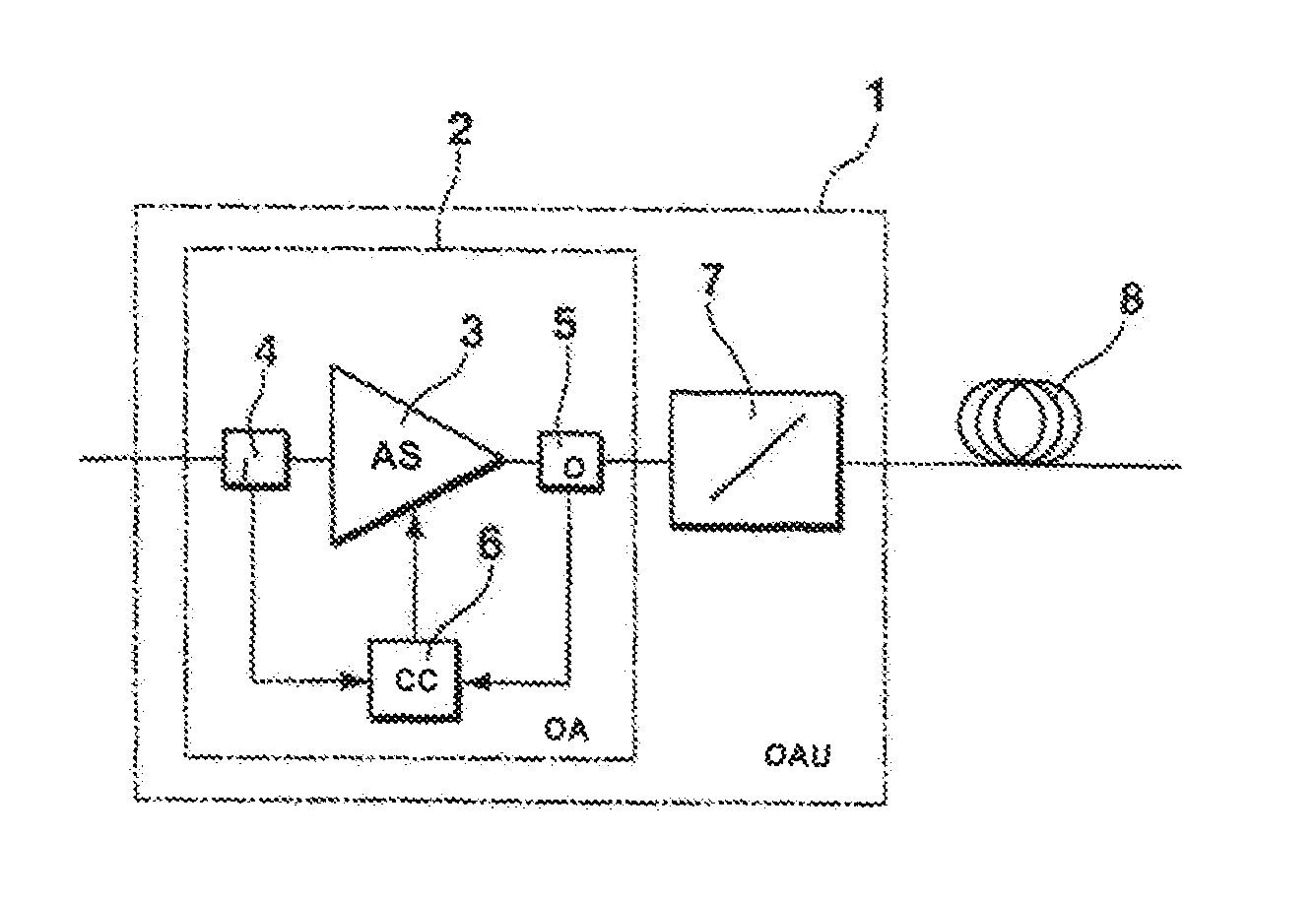
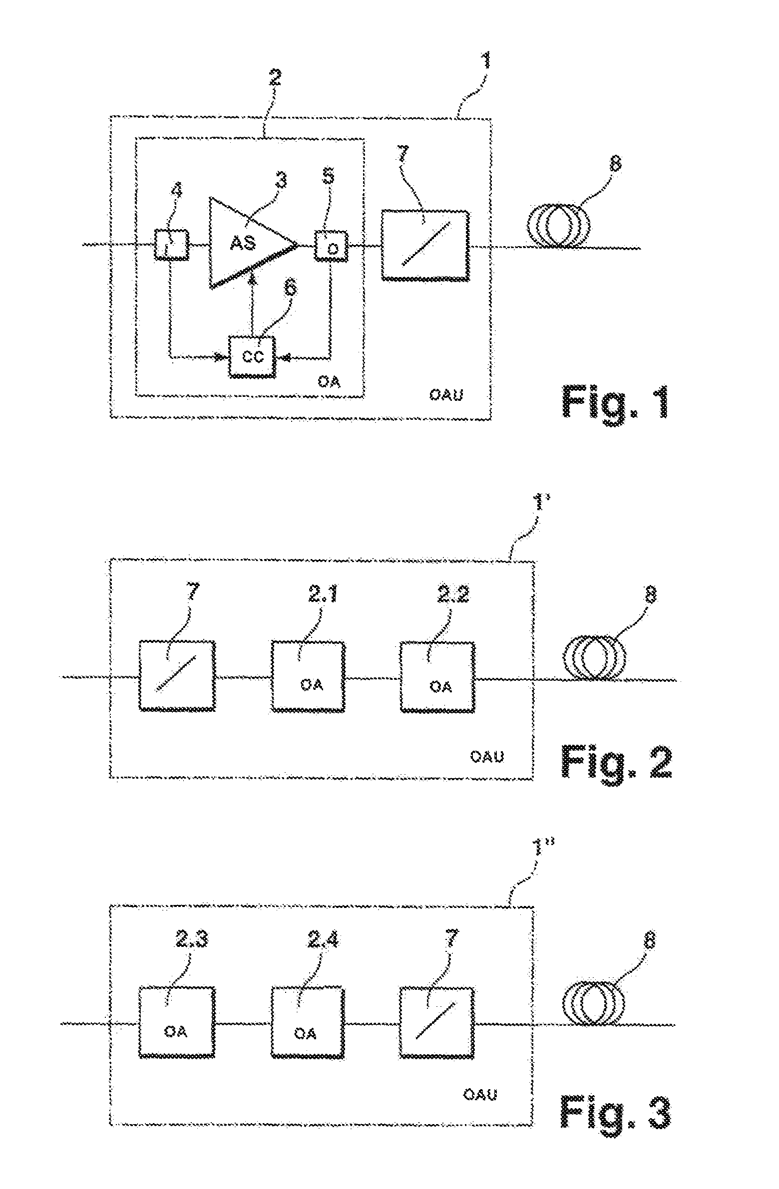
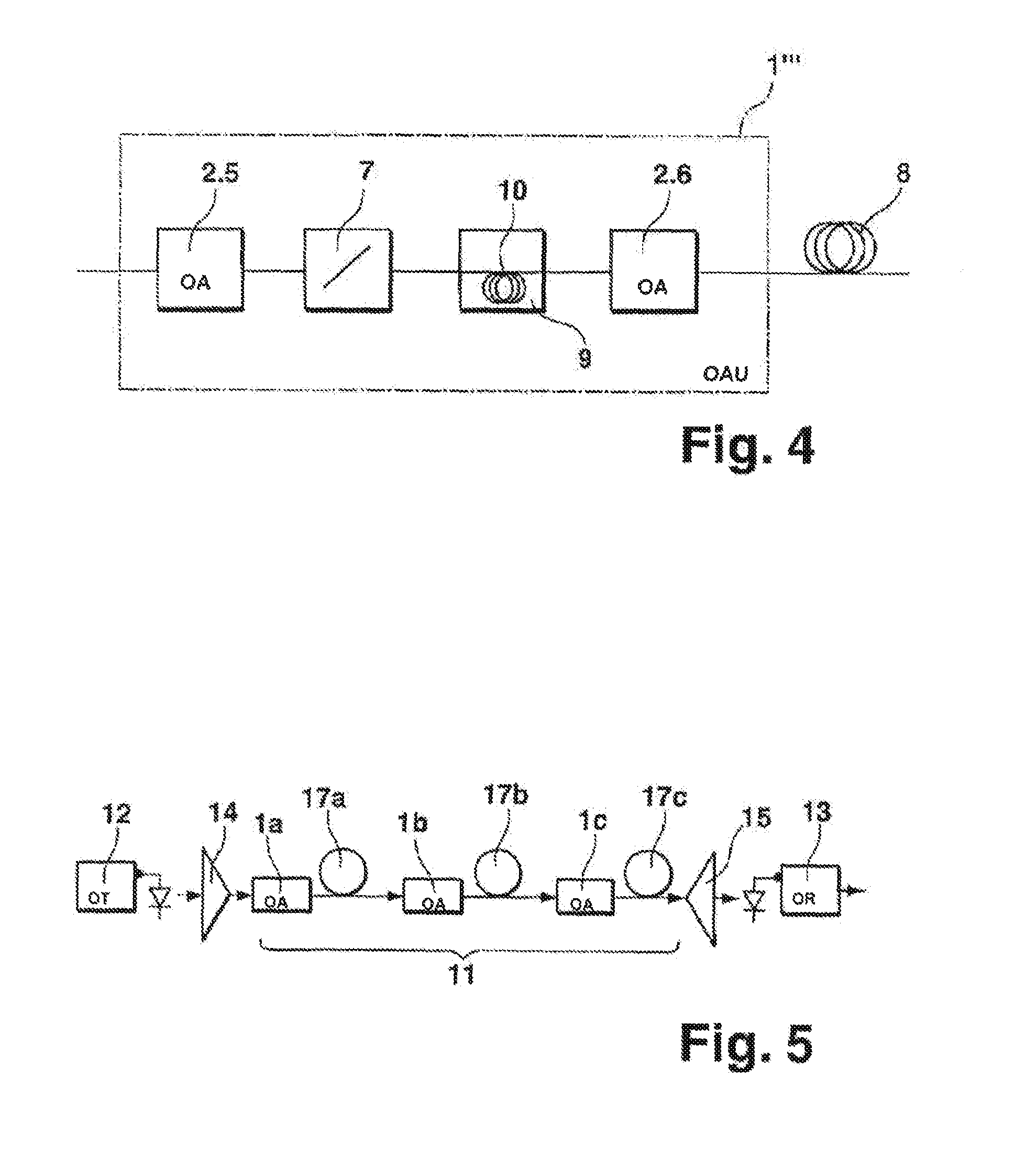
[0029]FIG. 1 shows an optical amplification unit 1 (OAU) with an optical amplifier 2 (OA), in the present case an EDFA, comprising an amplification stage 3 (AS) with a Gain Flattening Filter GFF (not shown) in order to compensate for the non flat gain of the Erbium doped Fiber, an input measuring device 4(I), an output measuring device 5(O) and a control circuit 6 (CC). The optical ampbtication unit 1 farther comprises a filter 7 and is connectable to an optical fiber span 8. Optical amplification units like the one shown in FIG. 1 are used in. a fiber optical transmission system as described below in connection with FIG. 5.

[0030]The input and output measuring devices 4, 5 are preferably a photodiode measuring the input and output power to the optical amplifier 2 or a property related to ...


PUM


Abstract

An optical amplification unit comprises at least one optical amplifier for amplifying an optical signal and a filter preceding or following the optical amplifier. The optical amplifier comprises a first measuring device for measuring a property of an input signal of the optical amplifier, a second measuring device for measuring a property of an output signal of the optical amplifier, and a control circuit for controlling a gain characteristic of the optical amplifier in dependence of said input and output signal properties. The filter exhibits a wavelength-dependent attenuation of the optical signal. The optical amplification unit is connectable to an optical fiber span and the filter is adapted to compensate for a span loss tilt caused by said optical fiber span. An optical transmission system with at least one such optical amplification unit and corresponding methods.

Description

[0001]The invention is based on a priority application EP 05 292 483.4 which is hereby incorporated by reference.TECHNICAL FIELD[0002]The invention relates to an optical amplification unit comprising at least one optical amplifier for amplifying an optical signal, the optical amplifier comprising a first measuring device for measuring a property of an input signal of the optical amplifier, a second measuring device for measuring a property of an output signal of the optical amplifier, and a control circuit for controlling a gain characteristic of the optical amplifier in dependence of the input and output signal properties, the optical amplification unit further comprising a filter.BACKGROUND OF THE INVENTION[0003]Optical amplification units are used e.g. in fiber optical transmission systems. Such systems normally comprise an optical fiber line with a plurality of optical fiber spans interconnected by a plurality of these optical amplification units.[0004]In such optical transmissi...

Claims


Application Information

Patent Timeline
Patent Type & Authority Patents(United States)
IPC IPC(8): H01S3/00H04B10/294H04B10/296
CPCH04B10/2941H04B10/296H01S3/1301
Inventor CHARLET, GABRIELSIMONNEAU, CHRISTIAN
Owner RPX CORP
Learn More