
Vacuum cleaning apparatus having a vacuum cleaning unit and a filter bag

a vacuum cleaning and filter bag technology, applied in the direction of cleaning equipment, electric equipment installation, suction filters, etc., can solve the problems of low rotational efficiency, no longer pursued concept, and inability to achieve successful product implementation in the mark

Active Publication Date: 2016-08-02
EUROLIFTERS HLDG NV
View PDF31 Cites 2 Cited by
  • Summary
  • Abstract
  • Description
  • Claims
  • Application Information

AI Technical Summary

Benefits of technology

[0042]This particular characteristic of the motor-fan unit is different from the characteristic of motor-fan units conventionally used in vacuum cleaning apparatuses to the effect that the latter produce a significantly higher negative pressure and provide a significantly lower maximum air flow.
[0044]According to a particularly preferred embodiment of the invention described above, the vacuum cleaning unit can with aperture 8 (40 mm) have an air flow rate of more than 250 W, preferably of more than 300 W, particularly preferably of more than 350 W. When the invention is thus embodied, fully satisfactory vacuuming operation across the entire filling operation of the filter bag can be guaranteed.
[0046]Preferably, the motor-fan unit can with aperture 8 (40 mm) exhibit a degree of efficiency according to EN 60335 of at least 20%, preferably of at least 25% and particularly preferably of at least 30%. This development of the invention leads to particularly energy-saving vacuum cleaning apparatuses.
[0049]This embodiment is based on the concept that a vacuum cleaning apparatus having a filter bag is with an empty filter bag operated at an input power that is set lower than the maximum power of the motor so that the input power to the motor can be increased correspondingly to the increased filling level of the filter bag. It has surprisingly shown that only a relatively small increase in the input power to the motor is required with filter bags having a tendency to clog of less that 15%, preferably having a tendency to clog of less than 10%, particularly preferably having a tendency to clog of less than 5%, in order to maintain constant the air flow at a level required for efficient vacuum cleaning, i.e. at least at 34 l / s. A vacuum cleaning apparatus could thereby be realized that can provide a substantially constant volume flow while the filter bag is continuously filled while simultaneously maintaining the maximum electrical input power to the vacuum cleaner below a predetermined value—which is acceptable from the perspective of power consumption—of 1200 W.
[0052]Particularly suited for such an apparatus is a motor-fan unit comprising a reluctance motor, preferably a switched reluctance motor. Such motors are characterized in particular by the fact that they are sturdy and durable.
[0056]Particularly suitable for the use in the apparatus according to the invention are vacuum cleaner bags with pleated filter material or with surface folds. Such vacuum cleaner bags are characterized by a particularly low air flow drop.

Problems solved by technology

This high rated input is required due to the high losses being caused by the separation principle, namely the loss for maintaining the high rotational speed of the dust-laden air in the cyclone separator.
However, due to the high clogging tendency of filter bags made of paper (approx.
While a constant air flow is thereby theoretically possible, it is very low.
For this reason, this concept was no longer pursued and could therefore not be implemented in the market as a successful product.

Method used


Image

  • Vacuum cleaning apparatus having a vacuum cleaning unit and a filter bag
  • Vacuum cleaning apparatus having a vacuum cleaning unit and a filter bag
  • Vacuum cleaning apparatus having a vacuum cleaning unit and a filter bag

Examples


Embodiment Construction

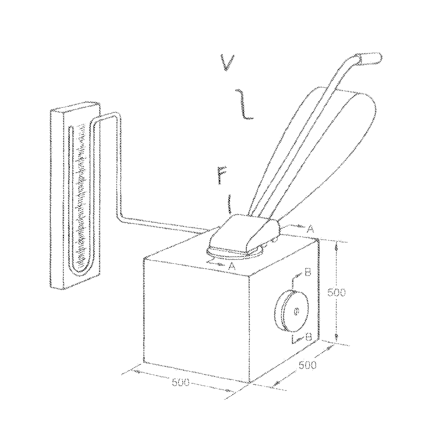
[0040]Given the aforementioned drawbacks of prior art, the invention is based on the object to provide a vacuum cleaning apparatus having a vacuum cleaning unit and filter bags, in which the nominal electrical rated input is significantly reduced, while the cleaning performance may not be reduced substantially as compared to vacuum cleaning devices that are available today with a much higher rated input.

[0041]This object is satisfied by a vacuum cleaning apparatus having the features of claim 1, i.e. by a vacuum cleaning apparatus having a vacuum cleaning unit and a filter bag, in which the vacuum cleaning unit has a motor-fan unit which is designed in such a way that the vacuum cleaning unit with filter bag inserted with aperture 0 generates a negative pressure between 30 kPa and 6 kPa, preferably a negative pressure of between 20 kPa and 8 kPa and particularly preferably a negative pressure between 15 kPa and 8 kPa and, with aperture 8 (40 mm), generates an air flow between 25 l / s...


PUM


Abstract

The invention relates to a vacuum cleaning apparatus having a vacuum cleaning unit and a filter bag, in which the vacuum cleaning unit has a motor-fan unit which is designed in such a way that the vacuum cleaning unit with filter bag inserted with aperture 0 generates a negative pressure between 13 kPa and 6 kPa, preferably a negative pressure of between 20 kPa and 8 kPa and particularly preferably a negative pressure between 15 kPa and 8 kPa and, with aperture 8 (40 mm), generates an air flow between 25 l / s and 49 l / s, preferably an air flow between 30 l / s and 45 l / a, and particularly preferably an air flow between 35 l / s and 45 l / s, and the filter bag is a disposable filter bag made of nonwoven material which, during the testing of the reduction in the maximum air flow with a partially filled dust container analogous to EN 60312, exhibits a reduction in the air flow of less than 15%, preferably less than 10%, particularly preferably less than 5%.

Description

[0001]This application claims the benefit under 35 U.S.C. §371 of International[0002]Application No. PCT / EP2013 / 053462, filed Feb. 21, 2013, which claims the benefit of European Patent Application No. 12002041.7, filed Mar. 22, 2012, which are incorporated by reference herein in their entirety.FIELD OF THE INVENTION[0003]The invention relates to a vacuum cleaning apparatus having a vacuum cleaning unit and a filter bag made of nonwoven material.DEFINITIONS[0004]The description of prior art and the invention are based on the following standards, below definitions and the following measurement methods.[0005]EN 60312: EN 60312 refers to the Standard in the version EN 60312:1998+A1: 2000+A2: 2004.[0006]EN 60335: EN 60335 refers to the Standard in the version EN 60335-2-2:2010.[0007]Determination of air data: The air data of a vacuum cleaner is determined according to EN 60312 section 2.8. The measuring device B in section 5.2.8 is presently used. Where motor-fan units are measured apart...

Claims


Application Information

Patent Timeline
Patent Type & Authority Patents(United States)
IPC IPC(8): A47L9/14A47L9/28
CPCA47L9/14A47L9/2821A47L9/2842A47L9/2857
Inventor SAUER, RALFSCHULTINK, JAN
Owner EUROLIFTERS HLDG NV
Learn More