System and method for monitoring the state of a plurality of machines connected via a computer network

a technology of computer network and monitoring system, applied in multiplex communication, digital output to print units, instruments, etc., can solve the problems of high steep rise in the cost of each recorder, and degrade the quality of characters and images printed by the printer, so as to achieve reliable monitoring and low cost

a technology of computer network and monitoring system, applied in multiplex communication, digital output to print units, instruments, etc., can solve the problems of high steep rise in the cost of each recorder, and degrade the quality of characters and images printed by the printer, so as to achieve reliable monitoring and low cost

US7383474B2Inactive Publication Date: 2008-06-03SEIKO EPSON CORP

Image

  • System and method for monitoring the state of a plurality of machines connected via a computer network
  • System and method for monitoring the state of a plurality of machines connected via a computer network
  • System and method for monitoring the state of a plurality of machines connected via a computer network

Examples


Embodiment Construction

[0141]Referring now to the accompanying drawings, there is shown a preferred embodiment of a machine monitor system according to the invention.

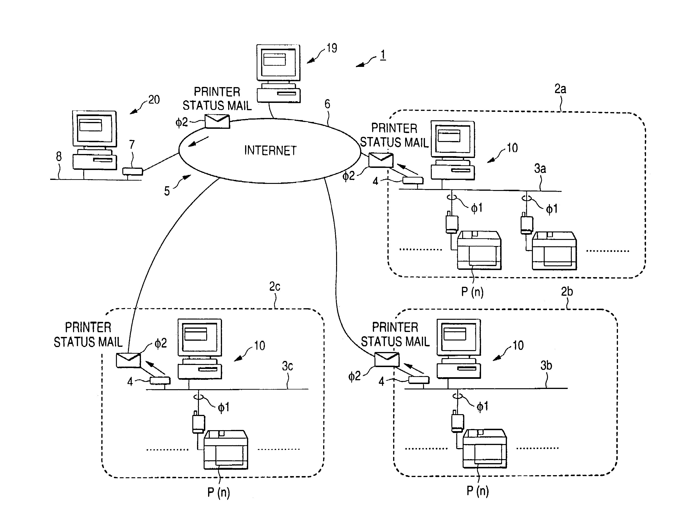
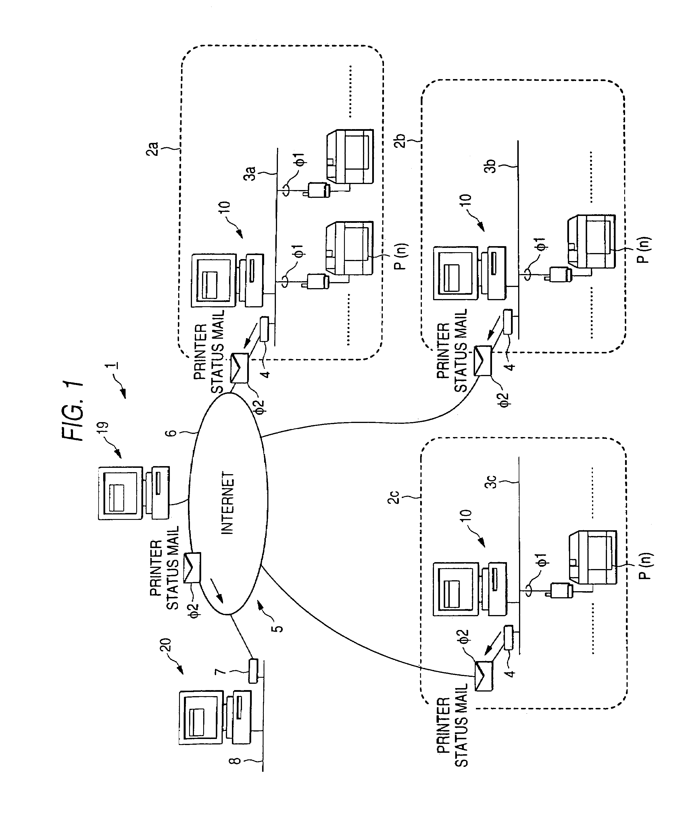
[0142]FIG. 1 is a schematic block diagram of a machine monitor system 1 according to an embodiment of the invention. The machine monitor system 1 is made up of one integrated monitor unit, which will be hereinafter referred to as console unit 20 and a plurality of local monitor units, which will be hereinafter referred to as agent unit 10.

[0143]Each agent unit 10 is connected to a first-type computer network, which will be hereinafter referred to as LAN (local area network), 3 (3a-3c) laid in a comparatively narrow area (first-type area) 2 (2a-2c) corresponding to a customer store, a business department of a customer company, or the like. In FIG. 1, three first-type areas 2 and three LANs 3 are shown; since the first-type areas 2 (2a-2c) are of the same configuration and the LANs 3 (3a-3c) are of the same configuration, only the first-type ar...


PUM


Abstract

Each agent unit gets status information indicating the state of each of network printers connected by a LAN from the network printers every first time period. Whenever each agent unit gets the status information from the network printer, it overwrites a status log data file with the gotten status information. Each agent unit converts all status information stored in the status log data file into status mail of electronic mail and transmits the status mail to a mail server every second time period longer than the first time period. On the other hand, a console unit accesses the mail server and reads the status mail in a proper time period to the console unit.

Description

CROSS-REFERENCE TO RELATED APPLICATIONS[0001]This application is a continuation of application Ser. No. 10 / 460,802, filed on Jun. 11, 2003 now U.S. Pat. No. 6,681,349, which is a continuation of application Ser. No. 10 / 154,987, filed on May 24, 2002, now U.S. Pat. No. 6,604,212, which is a division of application Ser. No. 09 / 226,332, filed on Jan. 6, 1999, now U.S. Pat. No. 6,430,711, the contents of all of which are herein incorporated by reference.BACKGROUND OF THE INVENTION[0002]1. Field of the Invention[0003]The present invention relates to a machine monitor system for monitoring the state of each of a plurality of machines connected via a computer network, a local monitor unit and an integrated monitor unit making up such a machine monitor system, a machine monitor method using such a machine monitor system, a computer-readable medium storing a program for causing a computer to function as a local monitor unit, and a computer-readable medium storing a program for causing a comp...

Claims


Application Information

Patent Timeline
03 Jun 2008
Publication
US7383474B2
IPC
G06F11/00; G06F3/12; B41J29/38; G06F3/048; G06F11/30; G06F13/00
CPC
G06F11/3013; G06F11/3055; G06F11/3068; G06F11/3093; H04L43/0817; G06F3/1208; G06F3/1219; G06F3/1229
Inventors
SEKIZAWA, HIROAKI