Liquid container and ink jet printing apparatus

a liquid container and ink jet technology, applied in the field of liquid containers, can solve the problems of increasing production costs, enlarge the size of the printer, and not always desirable display, so as to improve user visibility, ensure the degree of freedom, and facilitate the effect of light volum

Inactive Publication Date: 2008-06-10
CANON KK
View PDF11 Cites 29 Cited by
  • Summary
  • Abstract
  • Description
  • Claims
  • Application Information

AI Technical Summary

Benefits of technology

[0019]The present invention has been made in view of the above-mentioned technical background, and an object thereof is to obtain the information of a state in a liquid container with a favorable visibility without deteriorating the user's operability, through a liquid container simple in structure as well as low in production cost.
[0020]Another object of the present invention is to improve the visibility of the user and stabilize the operation of a light receiver section.
[0025]According to the present invention, it is possible to obtain a light volume favorable both for the improvement in the user's visibility in the display section and the operational stability in the light receiver section, by properly limiting a light volume emitted from the display section. Also, a structure is employed in which the light emitting source is separated from the display section and a light guiding section is provided on the liquid container for connecting the light therebetween. This makes it possible to obtain a structure for disposing the light emitting source and the display section at best positions, respectively, without needing the wiring for the power supply and the signal transmission / reception which interrupts the visibility and the operability of the user. Also, it is possible to ensure the degree of freedom for disposing the display section at a position at which the user's visibility is facilitated, whereby the user could obtain the predetermined information regarding the liquid container by viewing the light emitting state thereof.

Problems solved by technology

The provision of the display, however, is not always desirable since it causes to increase a production cost and enlarge a size of the printer, as well as requires to change a design of the printer.
Also, if the display is provided, it is not certain that the user clearly seizes the state of the ink tank at a glance.
Therefor, there is a problem in that the degree of arrangement freedom of each of the LED and the electric connecting part is restricted.
While it is thought to provide a large-sized PCB for covering both preferable positions for the electric connecting part and the LED, the production cost rises therefor.
When the structure disclosed in Japanese Patent Application Laid-open No. 4-275156 (1992) is applied to the printer capable of mounting a plurality of independent ink tanks for the respective colors, a structure for mounting the ink tanks onto the printer is limited.
However, the conductor wires in correspondence to the number of the ink alarming lamps are necessary, which complicates the wiring arrangement not only to cause the production cost to rise but also to deteriorate the visibility of the lamps by the conductor wires or the connection thereof.
In this case, however, the arrangement of the conductor wires is further complicated to cause the production cost to rise and also the attachment / detachment of the ink tank becomes difficult.
These problems have been further significant because the position at which the display is carried out to be visible by the user is preferably limited to the location or in the vicinity of operative means for the attachment / detachment of the ink tanks, due to the minimization in size or the multifunctioning of the printer.
Particularly, in a multifunction printer carrying a scanner in the upper portion of the printer, the display position is more restricted whereby the visibility and the operability are further demanded.
Even in this case, however, when the control section of the printer body recognizes an ink tank in which an amount of ink remaining therein is insufficient, it is necessary to specify such an ink tank to be supplied with a signal for the purpose of lighting the lamp based on such the recognition.
For example, when the ink tank has been mounted at an erroneous position, there might be a possibility in that another ink tank in which a sufficient amount of ink remains is displayed as no ink remains therein.
In this case, however, it is necessary to manufacture differently shaped ink tanks in correspondence to the respective ink colors or kinds, which is disadvantageous in production cost and / or efficiency on the recent trend that the number of ink tanks or kind of ink colors increases.
In this case, if an amount of emitted light is small, it may be difficult to be visible by the user although being sufficient for the light receiver section.
Contrarily, if the amount of emitted light is excessively large, an error is liable to occur between the adjacent ink tanks, resulting in the difficulty in the correct identification of the ink tank.

Method used


Image

  • Liquid container and ink jet printing apparatus
  • Liquid container and ink jet printing apparatus
  • Liquid container and ink jet printing apparatus

Examples


first embodiment

2. First Embodiment of Characteristic Structure

[0077]The user strongly desires to correctly identify the ink tank from which display section are emitted light. If the light volume emitted therefrom is excessively small, it is difficult to be seen. Contrarily, if excessively large, the erroneous identification is liable to occur between adjacent ink tanks. This is also true to the light receiver section in that it may receive the light not emitted from the ink tank in question but from that adjacent thereto.

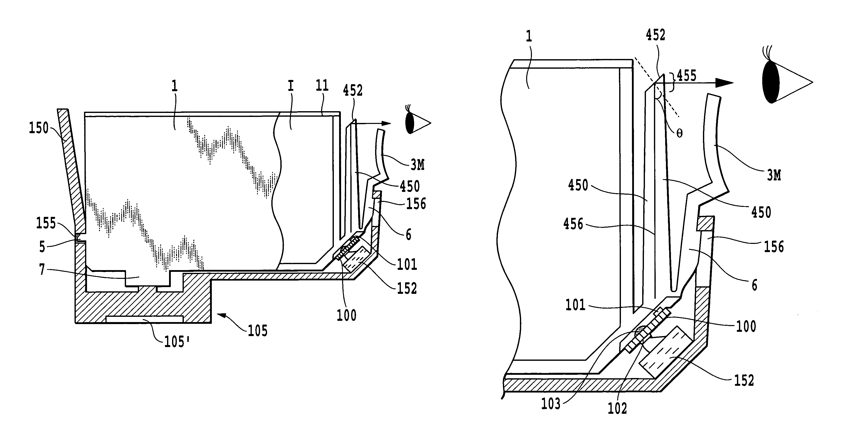
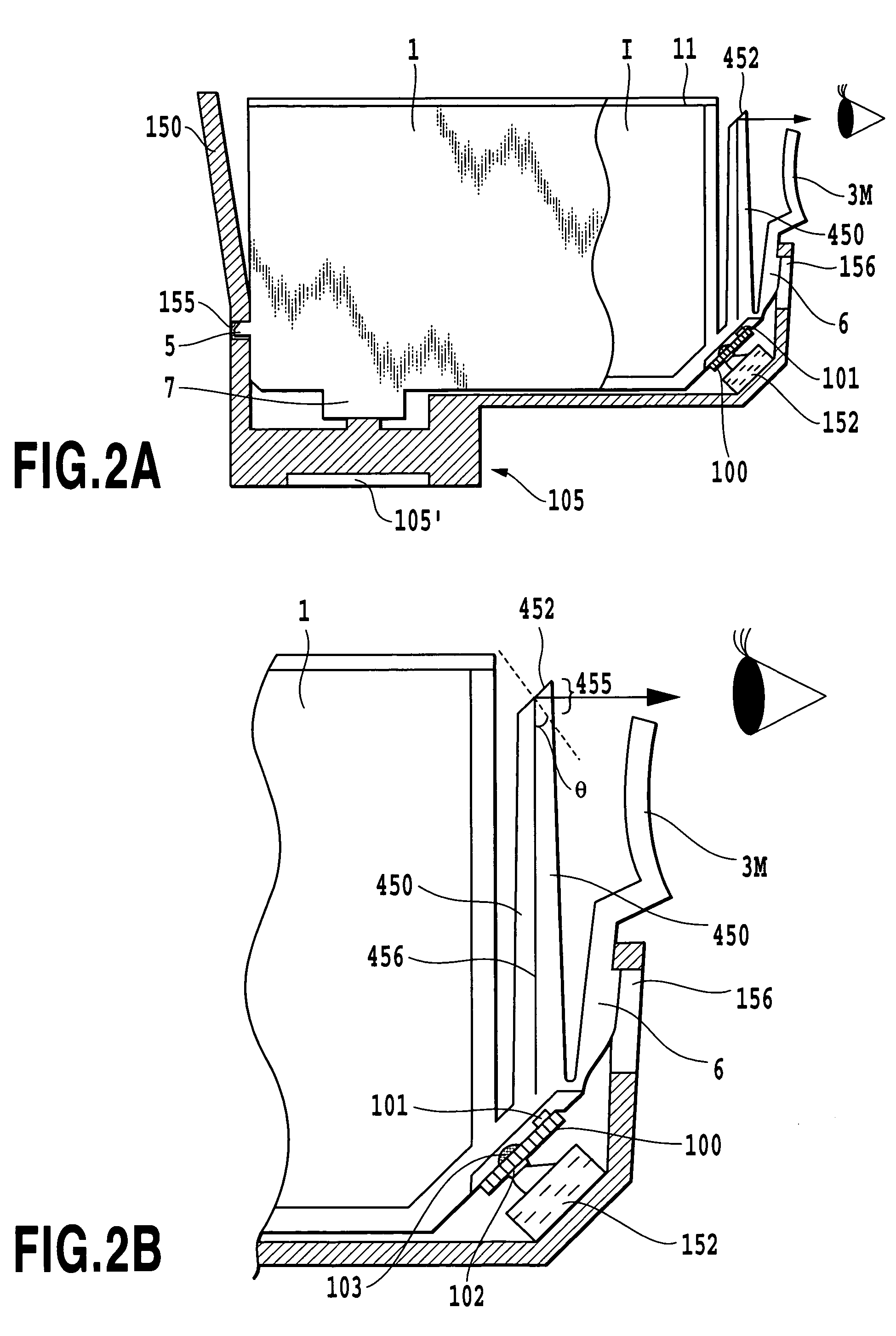
[0078]Accordingly, it is desirable to employ such a structure that the light emitted from the display section favorably reach the user and the light receiver section. Such a structure will be described below.

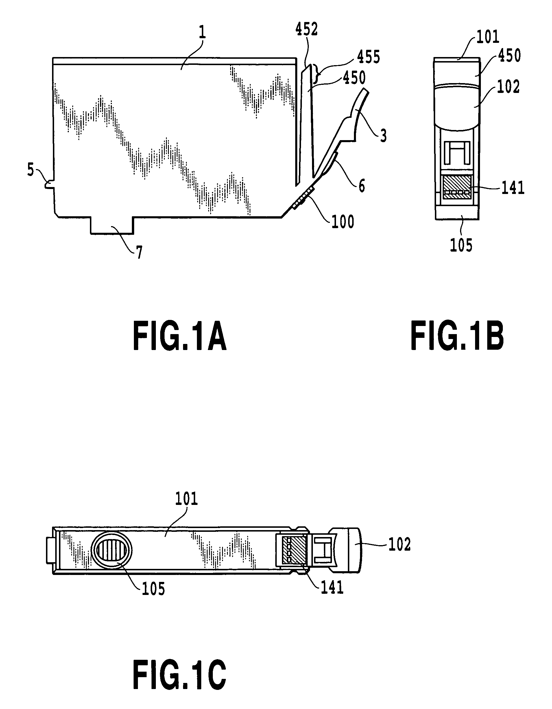
[0079]FIG. 8 is a perspective view of an ink tank employing a characteristic structure of the present invention in addition to the above-mentioned basic structure, FIGS. 9A, 9B, 9C and 9D are a side view, a top view, a bottom view and a front view, respectively, of the ink tan...

second embodiment

3. Second Embodiment of Characteristic Structure

[0096]FIGS. 12A, 12B, 12C and 12D are a side view, a top view, a bottom view and a front view, respectively, of a second embodiment according to the characteristic structure. FIG. 13A is a schematic illustration of a printing apparatus on which are mounted a plurality of ink tanks 1 shown in FIGS. 12A, 12B, 12C and 12D, while selecting a cyan tank 1C, a magenta tank 1M and a yellow tank 1Y as representatives. FIG. 13B illustrates a state in which the light receiver section is opposed to the display section of the ink tank 1M for the magenta ink in the arrangement shown in FIG. 13A. Further, in these drawings, the light guiding section 580 and the display section 585 are exaggeratedly depicted.

[0097]In the first characteristic structure, it is devised to emit the light from an upper part of the light guiding section 580 in which the light emission limiting member 21 is provided to define the display section. Contrarily, according to thi...


PUM


Abstract

A structure for informing a state of the ink tank by a light emitting section such as LED, capable of displaying such information at a position easily visible by the user and favorably sending the emitted light both to the user and a light receiver section on the printer side without needing electric wiring which may disturb the user's visibility or manipulation. The light emitting section is separated from the display section and a light guiding section is provided between the both. A member for suitably limiting the emission of light is provided in the display section. Thereby, it is possible to dispose the display section at the best position without needing the electric wiring on the ink tank and obtain a preferable light volume suitable both for the improvement in user's visibility and the stability of the operation of the light receiving section.

Description

BACKGROUND OF THE INVENTION[0001]1. Field of the Invention[0002]The present invention relates to a liquid container, more specifically to a liquid container wherein information relating to a state of the liquid container, such as a remaining amount of ink in an ink tank used on an ink jet printing apparatus is detected by a light-emitting means, for example, LED.[0003]2. Description of the Related Art[0004]Recently, as digital cameras have widely prevailed, uses are increasing wherein the printing is carried out while directly connecting a digital camera to a printer as a recording device without the intervention of a personal computer (PC). Such a printing is called as a “camera direct printing”. Further, a printing method is also increasing wherein a card type information storing medium used for the digital camera in a detachable manner is directly mounted to a printer so that data are transferred and printed. This is called as a “card direct printing” Also, a so-called multifunct...

Claims


Application Information

Patent Timeline
Patent Type & Authority Patents(United States)
IPC IPC(8): B41J29/393B41J2/175
CPCB41J2/17553B41J2/17566B41J2002/17573
Inventor KOTAKI, YASUOMATSUO, KEISUKEKITABATAKE, KENJIAMMA, HIROMASATASHIRO, NAOKI
Owner CANON KK
Why Eureka
Try Eureka