Pagewidth printhead having small print zone

a printhead and small technology, applied in printing, printing, power drive mechanisms, etc., can solve the problems of high power consumption, inability to meet the requirements of application, and limited nozzle packing density, so as to improve the operational characteristics of the printhead

Inactive Publication Date: 2008-06-10
SILVERBROOK RES PTY LTD +1
View PDF21 Cites 44 Cited by
  • Summary
  • Abstract
  • Description
  • Claims
  • Application Information

AI Technical Summary

Benefits of technology

[0023]In accordance with a fifth speci of the present invention, there is provided an inkjet printhead having a series of ink ejection nozzles for the ejection of ink, each of said nozzles interconnecting a nozzle chamber with an external atmosphere, each said nozzle having a first meniscus rim around which an ink meniscus normally forms, and an extended ink flow prevention rim spaced outwardly from said first meniscus rim and substantially encircling said first meniscus rim, arranged to prevent the flow of ink across the surface of said inkjet printhead.
[0057]an ink supply unit including at least one storage chamber for holding ink for supply to said printing arrangement, said ink supply unit including a series of spaced apart baffles configured so as to reduce the acceleration of the ink within the unit as may be induced by movement of the portable printer, whilst allowing for flows of ink to the printing arrangement in response to active demand therefrom.
[0059]In the preferred form, the printhead is an elongate page width printhead chip and the baffles in the ink supply are configured to reduce acceleration of the ink in a direction along the longitudinal extent of the printhead and corresponding ink supply unit. Preferably, the ink supply unit has a series of storage chambers for holding separate color inks.
[0076]In accordance with an additional aspect of the eleventh aspect of the present invention, there is provided an ink supply unit for supplying a multiple color page width ink supply printhead, comprising: a first elongated member containing a series of chambers for the storage of separate color inks and formed having dimensions refined to a first accuracy and having a first elongated cavity defined therein; a second elongated member including a series of wall elements and a second elongated cavity defined therein, the second elongated cavity being adapted for the insertion of a page width ink jet printhead, the wall elements mating with corresponding elements of the first elongated member to complete the formation of the series of chambers for the supply of ink to a series of slots formed in the back of the printhead when inserted in the second elongated cavity, wherein the second elongate member is formed having dimensions refined to a second accuracy which is higher then the first accuracy.

Problems solved by technology

This is because the two main contenders—thermal ink jet and piezoelectric ink jet—each have severe fundamental problems meeting the requirements of the application.
The most significant problem with thermal ink jet is power consumption.
This is approximately 100 times that required for these applications, and stems from the energy—inefficient means of drop ejection.
The high power consumption limits the nozzle packing density, as
The most significant problem with piezoelectric ink jet is size and cost.
This is not a significant problem at the current limit of around 300 nozzles per print head, but is a major impediment to the fabrication of page width print heads with 19,200 nozzles.

Method used


Image

  • Pagewidth printhead having small print zone
  • Pagewidth printhead having small print zone
  • Pagewidth printhead having small print zone

Examples


Embodiment Construction

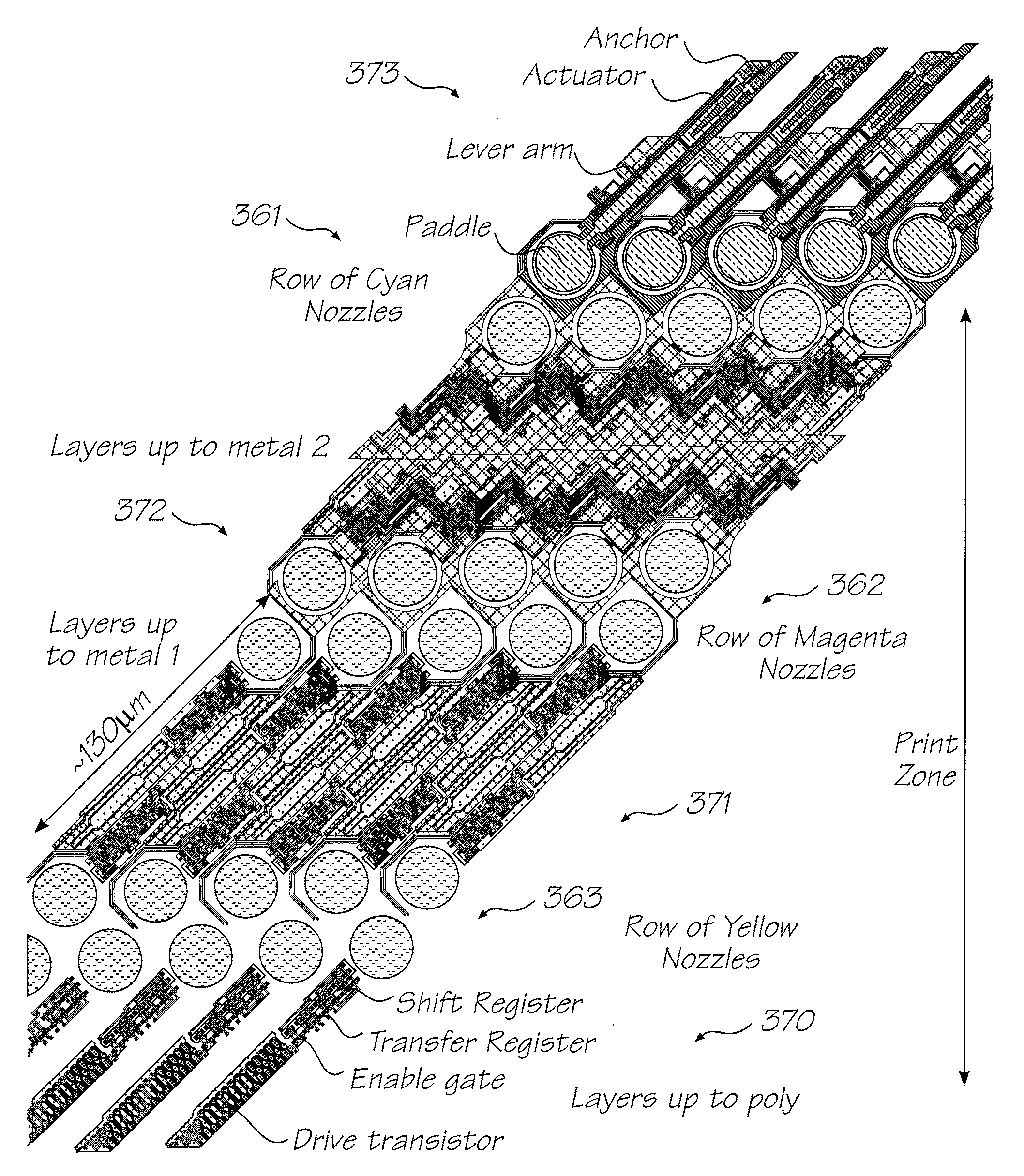
[0215]The preferred embodiment is a 1600 dpi modular monolithic print head suitable for incorporation into a wide variety of page width printers and in print-on-demand camera systems. The print head is fabricated by means of Micro-Electro-Mechanical-Systems (MEMS) technology, which refers to mechanical systems built on the micron scale, usually using technologies developed for integrated circuit fabrication.

[0216]As more than 50,000 nozzles are required for a 1600 dpi A4 photographic quality page width printer, integration of the drive electronics on the same chip as the print head is essential to achieve low cost. Integration allows the number of external connections to the print head to be reduced from around 50,000 to around 100. To provide the drive electronics, the preferred embodiment integrates CMOS logic and drive transistors on the same wafer as the MEMS nozzles. MEMS has several major advantages over other manufacturing techniques:

[0217]mechanical devices can be built with...


PUM


Abstract

A printer comprising a stationary printhead extending across a paper path is provided. The printhead has a plurality of color channels, each color channel comprising at least one nozzle row extending along the length of the printhead. Each nozzle in a color channel ejects the same colored ink. The printhead has a print zone of less than 10 mm, where the print zone is deifined as the distance covered by all nozzle rows of the printhead in a paper feed direction.

Description

CROSS REFERENCE TO RELATED APPLICATIONS[0001]The present application is a continuation-in-part of U.S. application Ser. No. 11 / 144,844 filed Jun. 6, 2005, which is a continuation of U.S. application Ser. No. 09 / 807,297 filed Aug. 13, 2001, now issued as U.S. Pat. No. 6,902,255, which is a 371 of PCT / AU99 / 00894 filed Oct. 15, 1999.FIELD OF THE INVENTION[0002]The present applicant has proposed an ink jet printing device which utilises micro-electro mechanical (mems) processing techniques in the construction of a print head driven by thermal bend actuator devices for the ejection of fluid such as ink from an array of nozzle chambers.[0003]Devices of this type have a number of limitations and problems.[0004]It is an object of the present invention to provide various aspects of an inkjet printing device which overcomes or at least ameliorates one of or more of the disadvantages of the prior art or which at least offers a useful alternative thereto.SUMMARY OF THE INVENTION[0005]In accorda...

Claims


Application Information

Patent Timeline
Patent Type & Authority Patents(United States)
IPC IPC(8): B41J2/04B41J2/05
CPCB41J2/04505B41J2/04516B41J2/04518B41J2/0452B41J2/04528B41J2/04541B41J2/04543B41J2/04553B41J2/04563B41J2/04565B41J2/0457B41J2/04571B41J2/04585B41J2/04588B41J2/0459B41J2/04591B41J2/04593B41J2/04596B41J2/04598B41J2/14427B41J2/155B41J2/1623B41J2/1628B41J2/1629B41J2/1631B41J2/1632B41J2/1635B41J2/1639B41J2/1642B41J2/1646B41J2/1648B41J25/005B41J2002/14491
Inventor SILVERBROOK, KIA
Owner SILVERBROOK RES PTY LTD
Why Eureka
Try Eureka