Method and system for performing surveillance

a surveillance system and surveillance method technology, applied in the field of image processing, can solve the problems of guards or system operators not being able to focus their attention, unable to automatically detect and track moving objects in the surveillance area, and objects in one camera's field of view may not be detected

Active Publication Date: 2008-06-10
SRI INTERNATIONAL
View PDF9 Cites 128 Cited by
  • Summary
  • Abstract
  • Description
  • Claims
  • Application Information

AI Technical Summary

Problems solved by technology

Such a system has a number of inherent flaws.
Specifically, these systems cannot automatically detect and subsequently track a moving object in the surveillance area.
The guard or system operator may not be able to focus his attention on each monitor simultaneously; therefore, creating a condition where a moving object in one camera's field of view may not be detected because the operator was attending a different monitor.
Another problem is that such systems cannot detect or otherwise process moving images when the camera is moving (i.e., either panning or tilting through different fields of view).
Such systems also cannot account for momentary image degradation (i.e., if the camera shakes because of wind or ground vibrations) or if a momentary dropout of the signal transmitted from the camera to the system occurs.

Method used


Image

  • Method and system for performing surveillance
  • Method and system for performing surveillance
  • Method and system for performing surveillance

Examples


Embodiment Construction

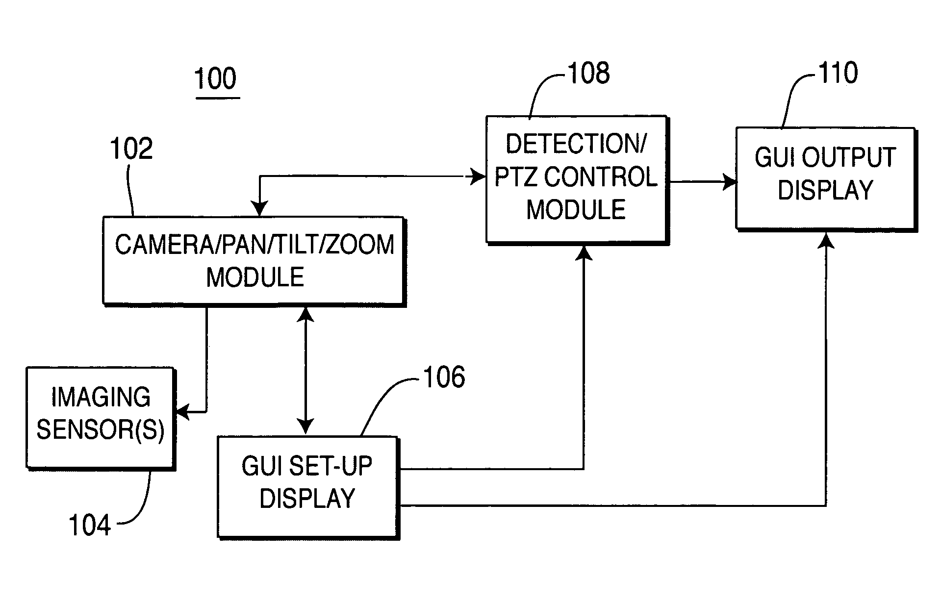
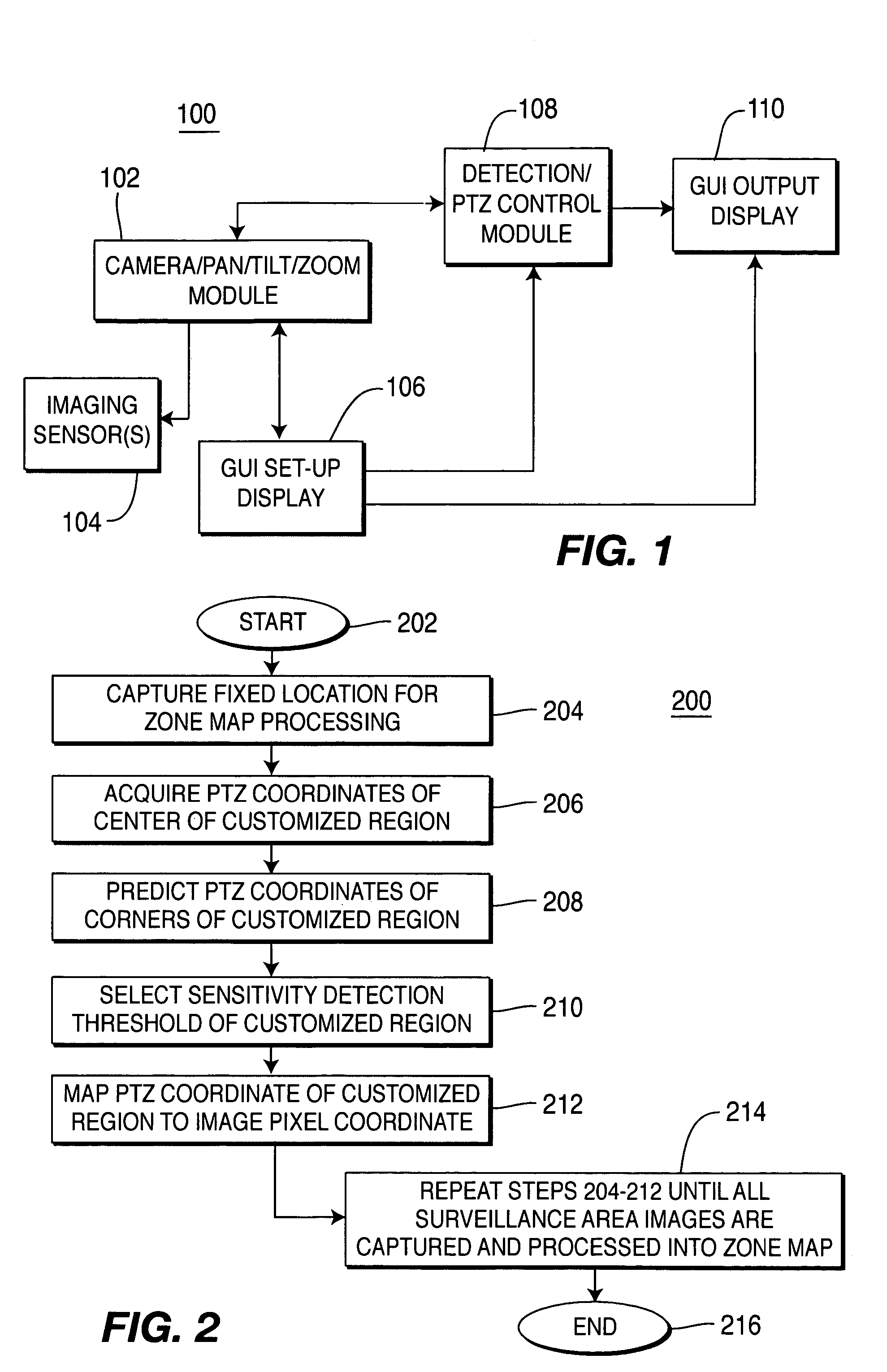
[0021]The present invention is a method and system for automatically detecting objects from a static or panning camera or cameras and controlling the operation of such camera(s) based upon object detection status. FIG. 1 depicts a block diagram of an object motion detection system 100 in accordance with the subject invention. The system 100 comprises a plurality of modules and interfaces that are interconnected in a manner so as to facilitate establishing a reference field of view for surveillance, obtaining and processing images from said surveillance area, automatically detecting moving objects in the surveillance area, displaying information regarding the status of the area under surveillance and selectively changing the mode of operation of the camera(s) connected to the system 100. In greater detail and by way of non-limiting example, the system 100 comprises a camera pan / tilt / zoom (PTZ) module 102 that controls the pan / tilt / zoom parameters of at least one imaging sensor 103 (e...


PUM


Abstract

A method and system for detecting moving objects and controlling a surveillance system includes a processing module adapted to receive image information from at least one imaging sensor. The system performs motion detection analysis upon captured images and controls the camera in a specific manner upon detection of a moving object. The image processing uses the camera's physical orientation to a surveillance area to facilitate mapping images captured by the camera to a reference map of the surveillance area. Using the camera orientation, a moving object's position (e.g., latitude, longitude and altitude) within a scene can be derived.

Description

CROSS-REFERENCE TO RELATED APPLICATIONS[0001]This application claims benefit of U.S. provisional patent application Ser. No. 60 / 419,893, filed Oct. 21, 2002, which is herein incorporated by reference.BACKGROUND OF THE INVENTION[0002]1. Field of the Invention[0003]The present invention generally relates to image processing. More specifically, the invention relates to a surveillance system for detecting static or moving objects from a static or panning camera.[0004]2. Description of the Related Art[0005]In order to provide security of a specific area, adequate surveillance methods and equipment for conducting such surveillance are necessary. Ordinarily, surveillance systems consists of one or more cameras placed on top of a pole or other location of a desired altitude so as to allow the camera a wide field of view that covers the area under surveillance. The cameras may be fixed or may be mounted on a mechanism that allows the cameras to pan (rotate on an axis to expand the angular fi...

Claims


Application Information

Patent Timeline
Patent Type & Authority Patents(United States)
IPC IPC(8): H04N7/18
CPCG06K9/00771G06T7/2066G08B13/19608G08B13/19641G08B13/1968G08B13/19682G08B13/19689H04N7/181G06T7/269G06V20/52
Inventor AGGARWAL, MANOJSAWHNEY, HARPREETSAMARASAKERA, SUPUNKUMAR, RAKESHBURT, PETERELEDATH, JAYANHANNA, KEITH J.
Owner SRI INTERNATIONAL
Why Eureka
Try Eureka