Packet protection method and transmission device in ring network, and program therefor

a packet protection and transmission device technology, applied in data switching networks, frequency-division multiplexes, instruments, etc., can solve the problems of deteriorating failure recovery rate and wasteful use of network bands by nni packets, and achieve the effect of increasing the failure recovery rate and efficient use of network resources

Inactive Publication Date: 2008-06-10
NEC CORP
View PDF23 Cites 26 Cited by
  • Summary
  • Abstract
  • Description
  • Claims
  • Application Information

AI Technical Summary

Benefits of technology

[0028]An object of the present invention is, when a failure occurs in a network, to efficiently use network resources to protect a packet, as well as increasing a failure recovery rate.

Problems solved by technology

When the NNI packet is thus unable to reach the transfer destination transmission device (when the NNI packet becomes an unreachable packet), the NNI packet wastefully uses a network band.
As a result, when the transmission device 100-4 connected to the actual use port 401 has a transmission device failure, although a transfer path exists from the terminal 210 to the terminal 211 using the spare port 402, the packet becomes an unreachable NNI packet to result in deteriorating a failure recovery rate.

Method used


Image

  • Packet protection method and transmission device in ring network, and program therefor
  • Packet protection method and transmission device in ring network, and program therefor
  • Packet protection method and transmission device in ring network, and program therefor

Examples


first embodiment

of the Present Invention

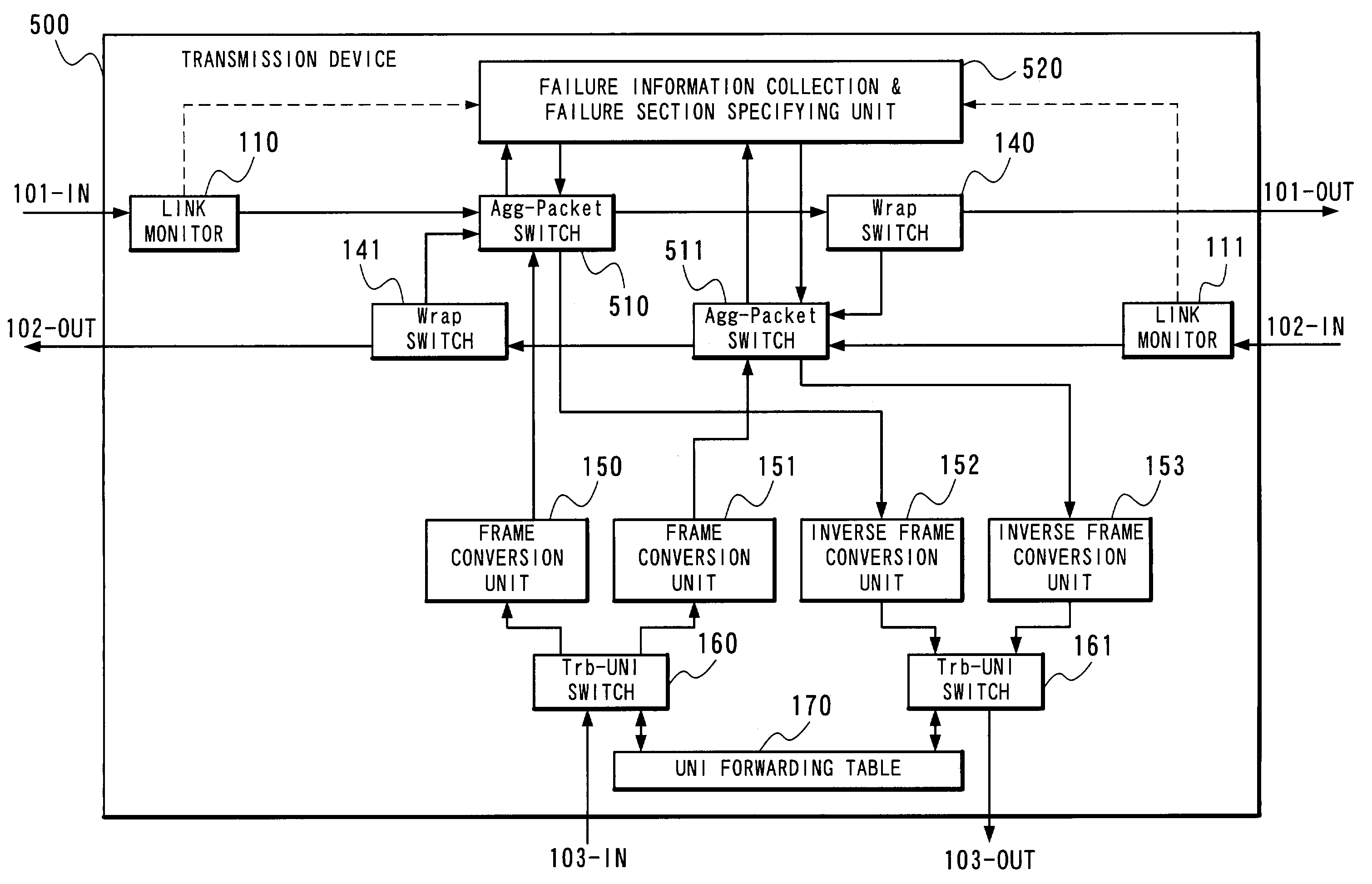
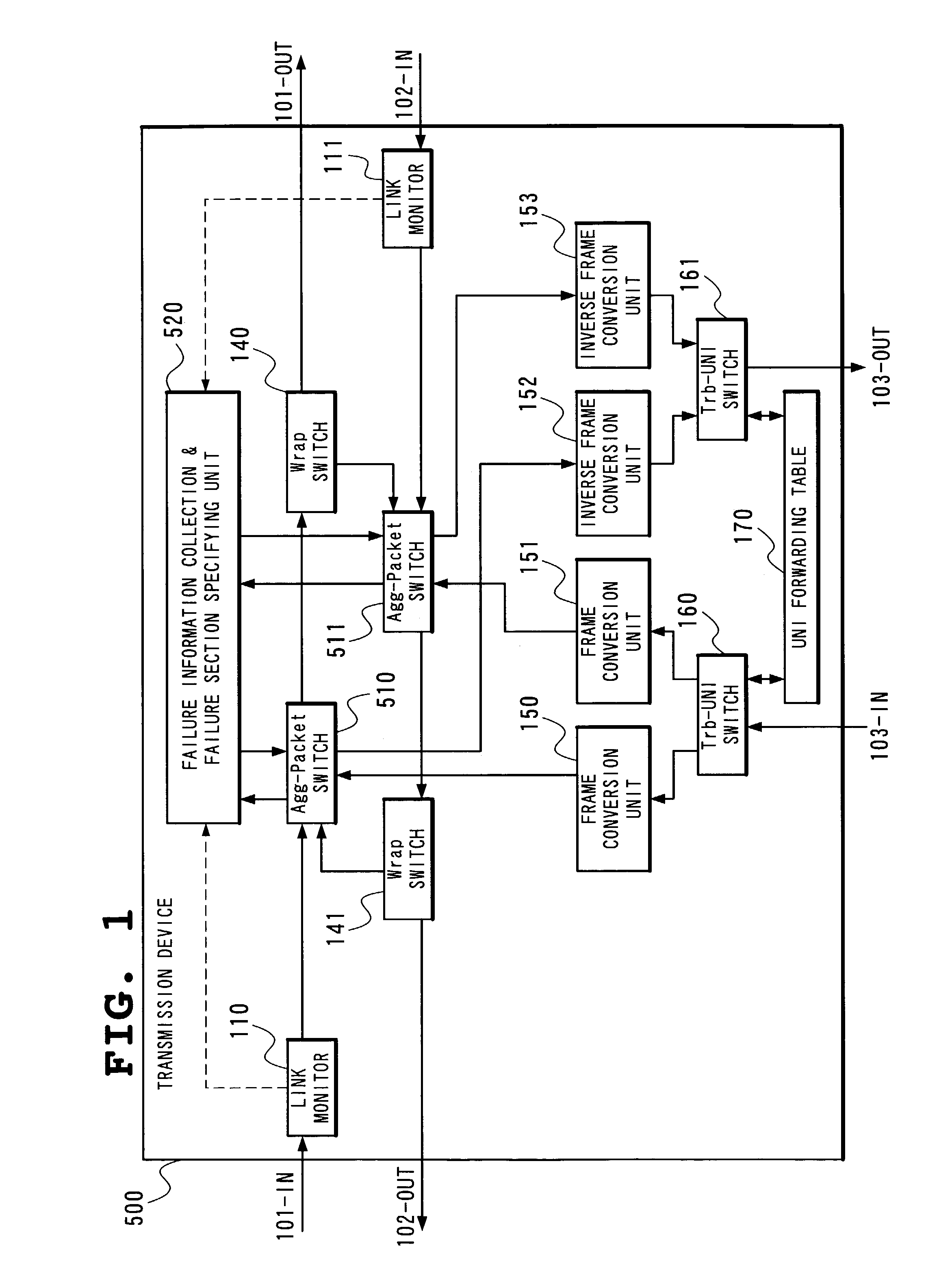
[0106]FIG. 1 is a block diagram showing an example of a structure of a transmission device 500 for use in realizing a first embodiment of a packet protection method in a ring network according to the present invention.

[0107]The transmission device 500 includes the link monitors 110 and 11, the Wrap switches 140 and 141, the frame conversion units 150 and 151, the inverse frame conversion units 152 and 153, the Trb-UNI switches 160 and 161, the UNI forwarding table 170, Agg-Packet switches 510 and 511 and a failure information collection & failure section specifying unit 520. Since the functions of the link monitors 110 and 111, the Wrap switches 140 and 141, the frame conversion units 150 and 151, the inverse frame conversion units 152 and 153 and the Trb-UNI switches 160 and 161 have been already described in detail in the Related Art, description will be here made only of newly added components.

[0108]The Agg-Packet switches 510 and 511 decipher a kind of an...

second embodiment

of the Present Invention

[0134]FIG. 6 is a block diagram showing an example of a structure of a transmission device for use in realizing a second embodiment of the above-described packet protection method in a ring network according to the present invention.

[0135]A transmission device 1000 shown in FIG. 6 differs from the transmission device 500 shown in FIG. 1 in additionally including Wrap detectors 1010 and 1011 and including a failure information collection & failure section specifying unit 1020 in place of the failure information collection & failure section specifying unit 520. In the following, description will be made only of operation of the Wrap detectors 1010 and 1011 and the related parts, and as to operation of the remaining parts, reference should be made to the description of the operation in the first embodiment and that of the operation of the Related Art.

[0136]The Wrap detector 1010 stores the transmission source NNI address #B applied by the frame conversion unit 1...

third embodiment

of the Present Invention

[0151]FIG. 10 is a block diagram showing an example of a structure of a transmission device for use in realizing a third embodiment of the packet protection method in a ring network according to the present invention. A transmission device 1400 shown in FIG. 10 is structured to further include squelch circuits 1410 and 1411 and Loop detectors 1420 and 1421 in the transmission device 500 shown in FIG. 1. In the following, description of the components which have been already made is omitted and only the newly added components and their peripheral portions will be described.

[0152]The Loop detectors 1420 and 1421 internally hold the addresses #A and #B applied to NNI packets by the frame conversion units 150 and 151, respectively. The loop detectors 1420 and 1421 each have the function of recognizing a transmission source NNI address and a transmission destination NNI address of an NNI packet applied from the link monitors 110 and 111, the function of determinin...


PUM


Abstract

Two transmission devices connected to a link in which a failure occurs turn back a ring. Other transmission device changes a transmission ring of an NNI packet which is a UNI packet whose transmission source is its own transmission device and which had been transmitted through the link before the failure occurs to have a reverse direction. In addition, each transmission device, upon receiving an NNI packet whose transmission destination NNI address is one or any one of a plurality of NNI addresses applied to its own transmission device, outputs the packet to a self-owned tributary port irrespectively of whether it is sent through an inner ring or an outer ring.

Description

BACKGROUND OF THE INVENTION[0001]1. Field of the Invention[0002]The present invention relates to a technique for packet protection in a packet transfer ring.[0003]2. Description of the Related Art[0004]With an increase in data system traffic whose representative is IP, efficient transmission of data is demanded from conventional communication service providers (hereinafter referred to as carriers) which provide transmission service mainly for voice. Together with the demand, as highly reliable protection method as “SONET, GR-1230-Core, Issue 3 Dec. 1996 Bellcore” on which conventional transmission networks base is demanded also in a data transmission network. Among highly reliable protection methods in data transmission networks is Spatial Reuse Protocol (hereinafter referred to as SRP)(RFC 2982 IETF).[0005]With reference to FIGS. 22 to 25, a protection method using the conventional SRP will be described.[0006]FIG. 22 is a block diagram showing an example of a structure of a transmi...

Claims


Application Information

Patent Timeline
Patent Type & Authority Patents(United States)
IPC IPC(8): H04J1/16H04L1/00H04J3/08H04J3/14H04L12/437H04L69/40
CPCH04J3/085H04J3/14H04L12/437H04L69/40
Inventor TAKAGI, KAZUO
Owner NEC CORP
Why Eureka
Try Eureka