Check patentability & draft patents in minutes with Patsnap Eureka AI!

Mulitcarrier CDMA transmission system and transmission method

a transmission system and multi-carrier technology, applied in the field of multi-carrier cdma transmission system and transmission method, can solve the problems of large deterioration in characteristics, complete loss of orthogonality of spreading codes of each user, etc., to achieve excellent multi-carrier transmission, excellent multi-carrier transmission, and elimination of interference from other users

Inactive Publication Date: 2008-06-10
FUJITSU LTD
View PDF12 Cites 4 Cited by
  • Summary
  • Abstract
  • Description
  • Claims
  • Application Information

AI Technical Summary

Benefits of technology

[0025]Accordingly, an object of the present invention is to so arrange it that the orthogonality of a spreading code will not be lost even when MC-CDMA transmission is performed on an uplink (i.e., in call origination from a mobile station).
[0026]Another object of the present invention is to avoid loss of the orthogonality of a spreading code even when MC-CDMA transmission is performed by applying beam forming in a downlink (i.e., in call origination from a base station).
[0027]A further object of the present invention is to realize excellent channel estimation accuracy even when individual pilots are used.

Problems solved by technology

Consequently, each subcarrier signal experiences independent fading user by user and orthogonality of the spreading code of each user is lost completely.
Accordingly, in a case where the MC-CDMA scheme for performing spreading in the frequency domain is applied to the uplink, a large deterioration in characteristics occurs.
Even when beam forming is carried out, therefore, the orthogonality of spreading codes is lost and the characteristic deteriorates significantly.
In actuality, however, the side lobes of the beam interfere with other users and, hence, the influence of deterioration of characteristics due to loss of orthogonality is great.
In such case, fading sustained by users in different directional zones becomes independent, orthogonality of spreading codes is lost and characteristics deteriorate markedly.
In actuality, however, side lobes SB of the beam BM interfere with other users, as shown in FIG. 23, and, hence, the influence of deterioration of characteristics due to loss of orthogonality is great.
The greater the number of individual pilots, therefore, the greater the decline in the accuracy of channel estimation.

Method used


Image

  • Mulitcarrier CDMA transmission system and transmission method
  • Mulitcarrier CDMA transmission system and transmission method
  • Mulitcarrier CDMA transmission system and transmission method

Examples


first embodiment

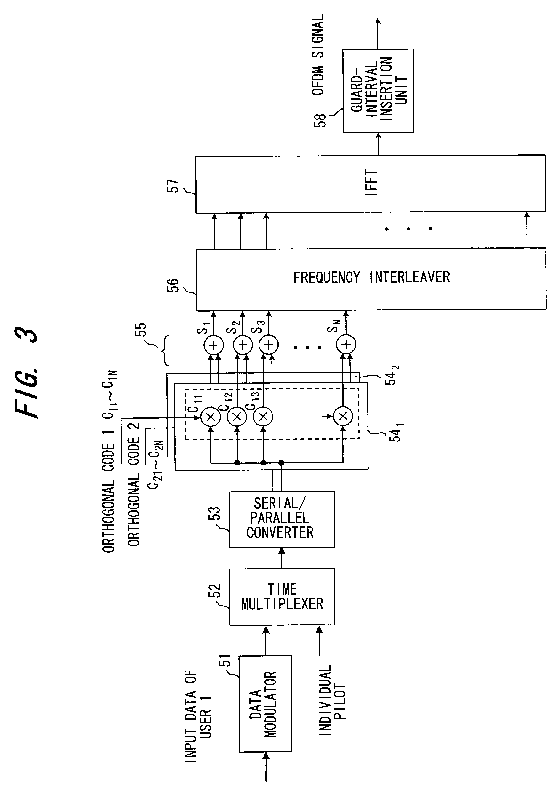
[0071](B) First Embodiment

[0072]FIG. 3 is a block diagram of the transmitting side of a mobile station in the case of an uplink when subcarriers are assigned exclusively on a per-user basis. FIG. 3 illustrates a case where subcarriers SC11 to SC1N are used upon being assigned to user 1, and multicode multiplexing is performed upon assigning first and second orthogonal codes C11 to C1N, C21 to C2N to user 1. The number N of subcarriers possessed exclusively by one user is the same as the spreading rate, and other users also perform multicode multiplexing similarly using other subcarrier sets. The number N of subcarriers possessed exclusively by one user may be a multiple of the spreading rate.

[0073]A data modulator 51 modulates transmit data and converts it to a complex baseband signal sequence (symbol sequence) having an in-phase component and a quadrature component. A time multiplexer 52 time-multiplexes the pilot of the plurality of symbols to the front of the transmit data. A ser...

second embodiment

[0084](C) Second Embodiment

[0085]FIG. 5 is a block diagram of the transmitting side (a block diagram of a base station) in a case where beam forming is used in a downlink (origination of a call from the base station). This is a case where a transmission is made by beam forming using a directional beam on a per-user basis. Further, the Figure illustrates a case where N-number of subcarriers SC11 to SC1N are used upon being assigned exclusively to user 1, and multicode multiplexing is performed upon assigning first and second orthogonal codes C11 to C1N, C21 to C2N to user 1. With regard also to other users, N-number of other subcarriers are used upon being assigned exclusively and a plurality of orthogonal codes are assigned to perform multicode multiplexing. The subcarrier signals of each of the users are frequency-multiplexed by a frequency multiplexer 158.

[0086]A data modulator 151 modulates transmit data of user 1 and converts it to a complex baseband signal sequence (symbol sequ...

third embodiment

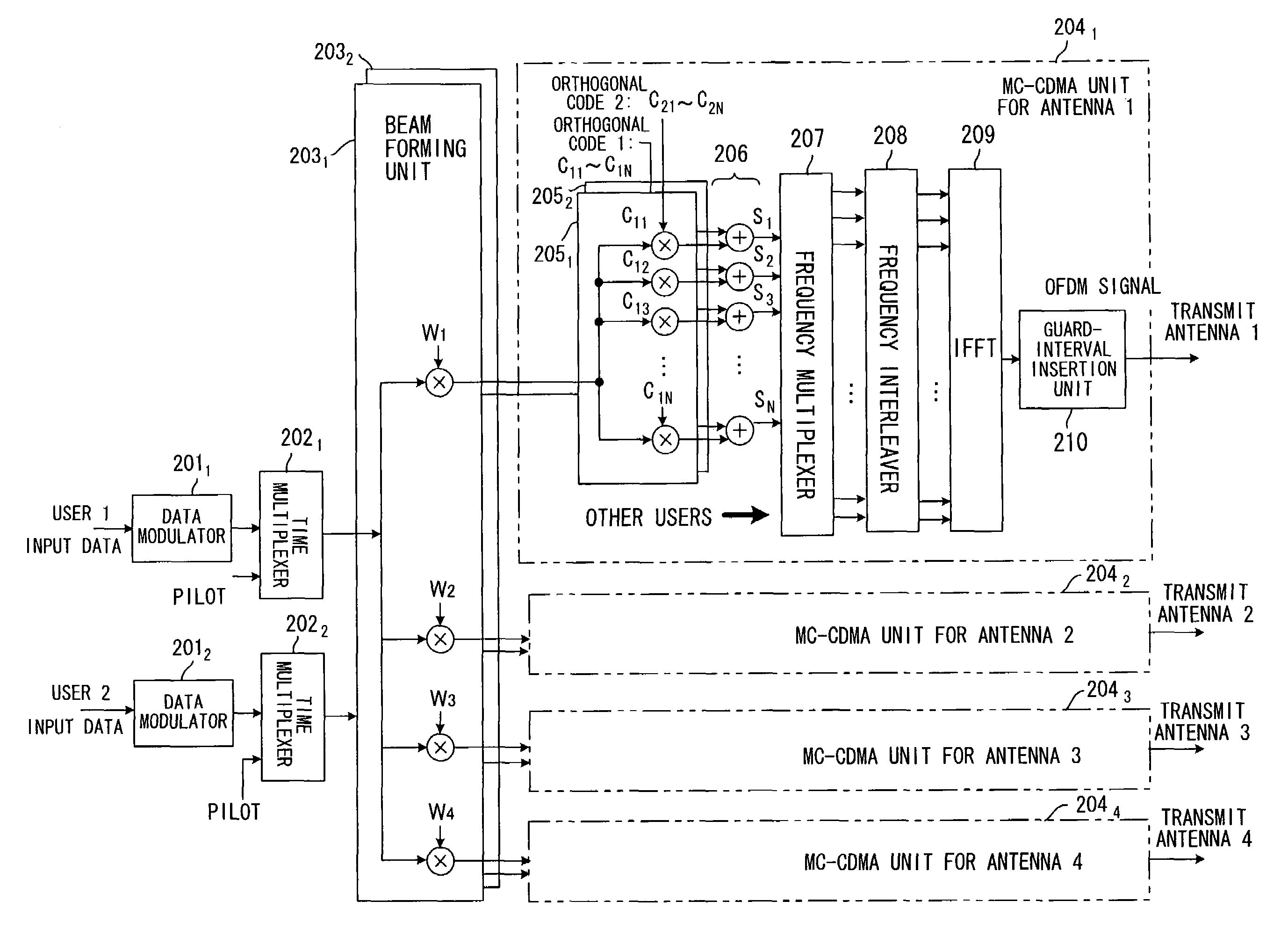
[0098](D) Third Embodiment

[0099]FIG. 9 is a block diagram of a base station according to a third embodiment of the present invention. It can be assumed that the mobile station will have a structure similar to that shown in FIG. 6. The third embodiment is applicable to a case where the base station transmits, using the same directional beam, to a plurality of users belonging to the same directional zone. The Figure illustrates a case where users 1, 2 are present in the same directional zone, N-number of subcarriers conforming to this directional zone have been assigned to users 1, 2, and different sets of orthogonal codes C11 to C1N, C21 to C2N have been assigned to users 1, 2.

[0100]A data modulator 2011 modulates transmit data of user 1 and converts it to a complex baseband signal sequence (symbol sequence) having an in-phase component and a quadrature component. A time multiplexer 2021 time-multiplexes the pilot of the plurality of symbols to the front of the transmit data of user ...


PUM


Abstract

In multicarrier transmission for multiplying transmit data individually by each code constituting orthogonal codes and transmitting each result of multiplication by a prescribed subcarrier, a plurality of different subcarriers are assigned exclusively to each user and each user performs multicarrier transmission of the transmit data by the subcarriers assigned. Further, a base station assigns a plurality of different subcarriers to each user exclusively, applies beam-forming processing on a per-user basis and performs multicarrier transmission of transmit data to each user by the subcarriers assigned.

Description

[0001]This application is a continuation of international application number PCT / JP01 / 07451, filed Aug. 30, 2001 and is still pending.BACKGROUND OF THE INVENTION[0002]This invention relates to a multicarrier CDMA transmission system and transmission method. More particularly, the invention relates to a multicarrier CDMA transmission system and transmission method for subjecting transmit data to a serial-to-parallel conversion, multiplying each symbol of the obtained parallel data individually by each code constituting orthogonal codes, and multicarrier-transmitting each result of multiplication by a prescribed subcarrier.[0003]Multicarrier modulation schemes have become the focus of attention as next-generation mobile communication schemes. Using multicarrier modulation not only makes it possible to implement wideband, high-speed data transmission but also enables the effects of frequency-selective fading to be mitigated by narrowing the band of each subcarrier. Further, using ortho...

Claims


Application Information

Patent Timeline
IPC IPC(8): H04B1/00H04B1/707H04J13/00H04J13/18H04L5/02H04L27/26
CPCH04B7/0669H04L5/026
Inventor SEKI, HIROYUKIJITSUKAWA, DAISUKETANAKA, YOSHINORI
Owner FUJITSU LTD
Features
  • R&D
  • Intellectual Property
  • Life Sciences
  • Materials
  • Tech Scout
  • Unparalleled Data Quality
  • Higher Quality Content
  • 60% Fewer Hallucinations
Learn More