
Obstacle recognition apparatus and method, obstacle recognition program, and mobile robot apparatus

Inactive Publication Date: 2008-06-10
SONY CORP
View PDF22 Cites 97 Cited by
  • Summary
  • Abstract
  • Description
  • Claims
  • Application Information

AI Technical Summary

Benefits of technology

[0008]It is therefore an object of the present invention to overcome the above-mentioned drawbacks of the related art by providing an obstacle recognition apparatus, obstacle recognition method and an obstacle recognition program, capable of accurately extracting a floor surface to recognize an obstacle on the floor.
[0014]According to the present invention, a two-dimensional distance sensor such as a stereoscopic camera or the like is used as each of the plurality of imaging means. With the distance sensors, it is possible to extract a floor surface more robustly and accurately from a relation between the plane detection by the image recognition and robot posture.

Problems solved by technology

Since this method permits to detect only an obstacle having a predetermined height, however, the robot cannot recognize any obstacle such as a small step (lower than the predetermined height) or a hole or concavity in the floor.
However, the method adopted in the quadrupedal walking robot can range only one point (or several points when the distance detection is repeatedly tried with the robot posture being changed) and so can hardly detect the surroundings of the robot satisfactorily.
Also, this method can detect one point at each time of distance detection, it is not so highly reliable in terms of the accuracy of distance detection.

Method used


Image

  • Obstacle recognition apparatus and method, obstacle recognition program, and mobile robot apparatus
  • Obstacle recognition apparatus and method, obstacle recognition program, and mobile robot apparatus
  • Obstacle recognition apparatus and method, obstacle recognition program, and mobile robot apparatus

Examples


Embodiment Construction

[0048]An embodiment of the present invention will be described herebelow with reference to the accompanying drawings. The embodiment is an application of the obstacle recognition apparatus according to the present invention to a bipedal walking robot apparatus.

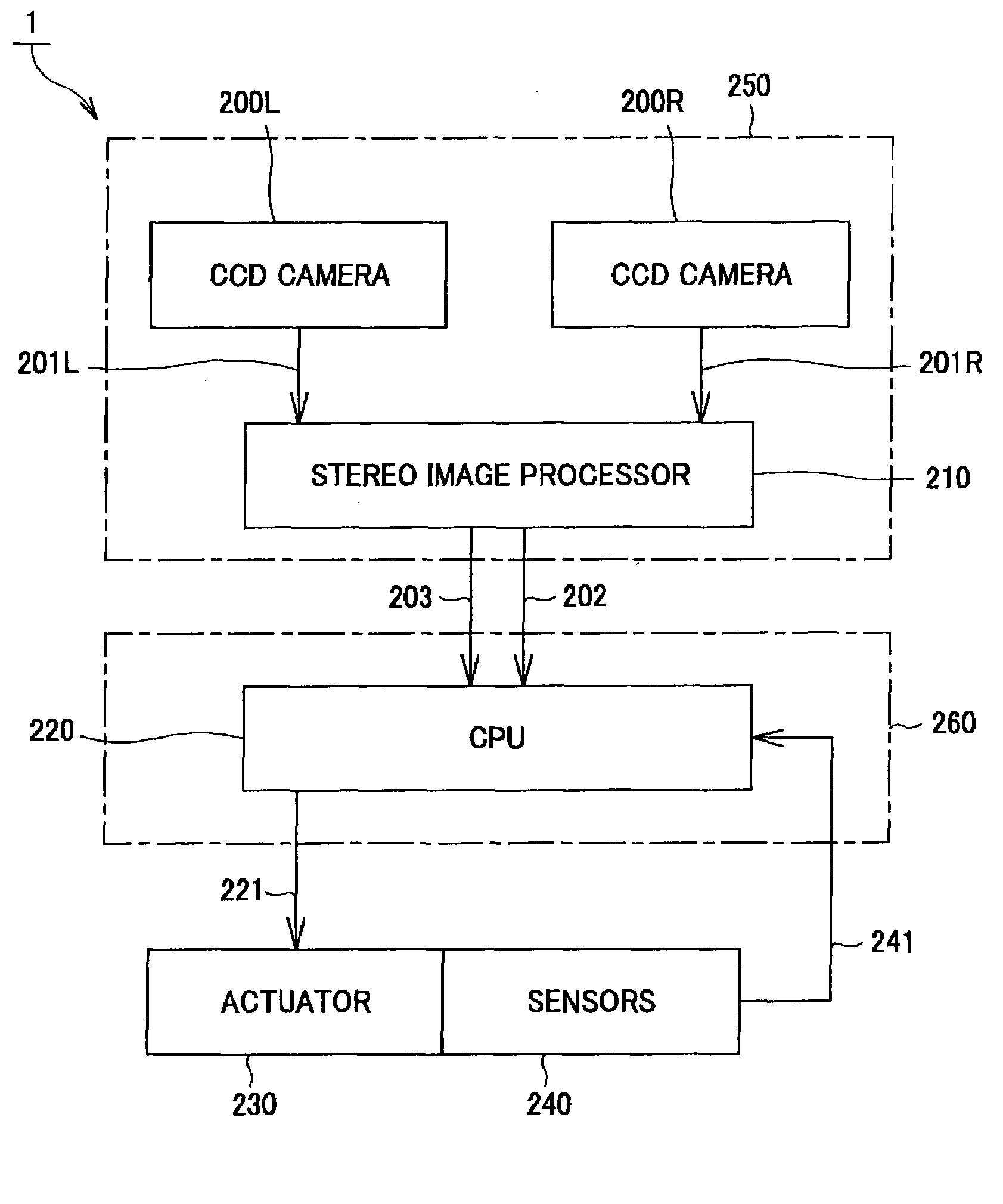
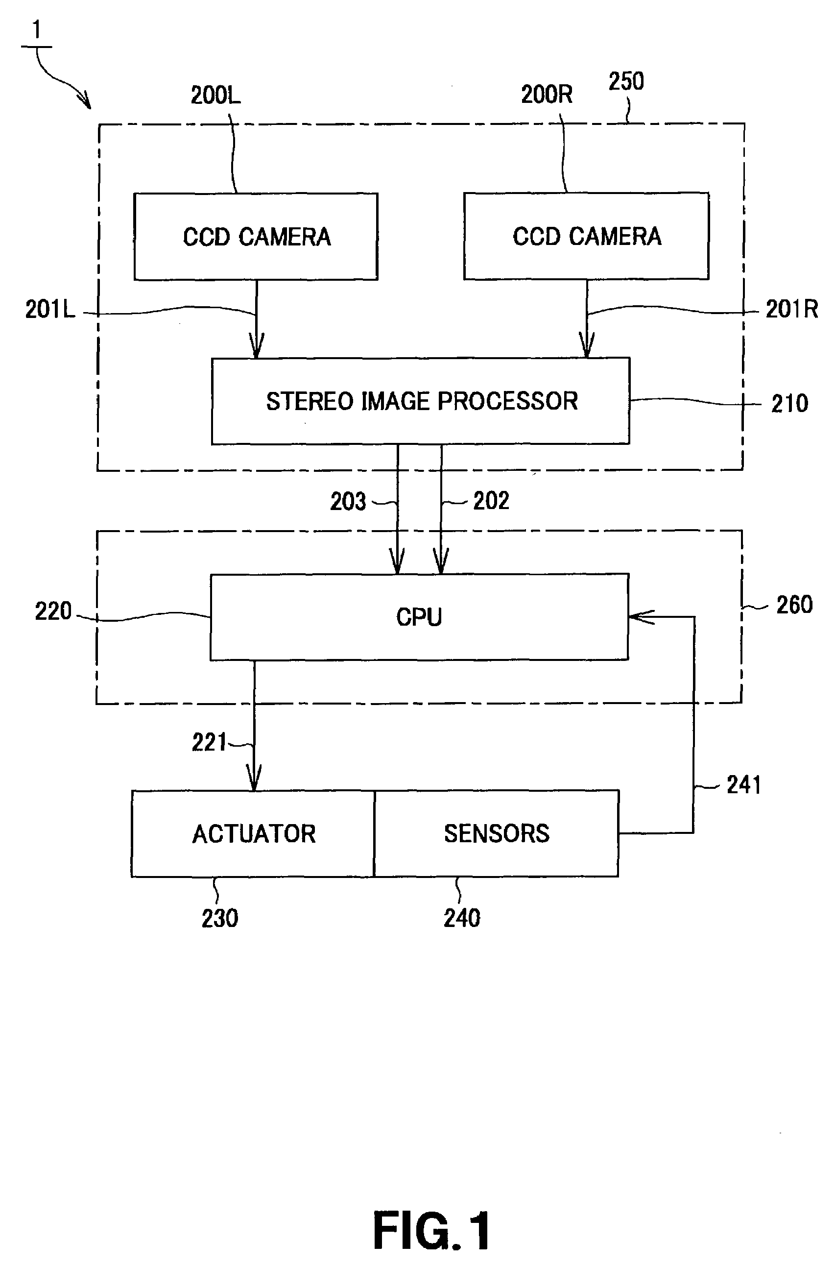
[0049]Referring now to FIG. 1, there is schematically illustrated in the form of a block diagram of the bipedal walking robot apparatus. As shown in FIG. 1, the robot apparatus is generally indicated with a reference 1, and includes a head unit 250. The head unit 250 has two CCD cameras 200R and 200L provided herein and a stereo image processor 210 provided behind the CCD cameras 200R and 200L. The two CCD cameras (will be referred to as “right CCD camera 200R” and “left CCD camera 200L”, respectively, hereunder) provide a right image 201R and left image 201L, respectively. These images 201R and 201L are supplied to the stereo image processor 210. The stereo image processor 210 calculates disparity information (distance inform...


PUM


Abstract

An obstacle recognition apparatus is provided which can recognize an obstacle by accurately extracting a floor surface. It includes a distance image generator (222) to produce a distance image using a disparity image and homogeneous transform matrix, a plane detector (223) to detect plane parameters on the basis of the distance image from the distance image generator (222), a coordinate transformer (224) to transform the homogeneous transform matrix into a coordinate of a ground-contact plane of a robot apparatus (1), and a floor surface detector (225) to detect a floor surface using the plane parameters from the plane detector (223) and result of coordinate transformation from the coordinate transformer (224) and supply the plane parameters to an obstacle recognition block (226). The obstacle recognition block (226) selects one of points on the floor surface using the plane parameters of the floor surface detected by the floor surface detector (225) and recognizes an obstacle on the basis of the selected point.

Description

BACKGROUND OF THE INVENTION[0001]1. Field of the Invention[0002]The present invention generally relates to an obstacle recognition apparatus and method, and more particularly to an obstacle recognition apparatus, obstacle recognition method and an obstacle recognition program, applied in a mobile robot apparatus to recognize an obstacle on a floor, and a mobile robot apparatus.[0003]This application claims the priority of the Japanese Patent Application No. 2002-073388 filed on Mar. 15, 2002, the entirety of which is incorporated by reference herein.[0004]2. Description of the Related Art[0005]Needless to say, it is important for the autonomous robot to be able to recognize its surroundings for programming a route it should take and move along the route. The conventional mobile or locomotive robots include a wheeled type robot, walking type robot (bipedal and quadrupedal), etc. The wheeled type robot provided around it ultrasonic sensors disposed in parallel to the floor surface to ...

Claims


Application Information

Patent Timeline
IPC IPC(8): G06K9/00B25J5/00G01B11/00B25J19/04G01B11/24G01B11/245G01C3/06G01C22/00G05D1/02G06F17/10G06F19/00G06T1/00G06T7/00H04N7/00H04N7/18H04N15/00
CPCG06K9/00664G06T7/0022G06T7/97G06V20/10
Inventor SABE, KOHTAROKAWAMOTO, KENTAOHASHI, TAKESHIFUKUCHI, MASAKIOKUBO, ATSUSHIGUTMANN, STEFFEN
Owner SONY CORP
Learn More