Hydraulic fast locking and loosening device for bearing assemblies of rolling-mill cylinders, and corresponding method of use

a technology of hydraulic fast locking and loosening device, which is applied in the direction of bearings, shafts, rod connections, etc., can solve the problems of increasing the risk of injury to maintenance staff, increasing the risk of equipment damage, and difficulty in tightening, so as to achieve fast and simple construction, simple structure, and simple structure

Inactive Publication Date: 2008-06-17
DANIELI & C OFF MEC SPA
View PDF14 Cites 20 Cited by
  • Summary
  • Abstract
  • Description
  • Claims
  • Application Information

AI Technical Summary

Benefits of technology

[0007]Consequently, the purpose of the present invention is to overcome the problems discussed above of known state-of-the-art fast locking and loosening devices, by providing a hydraulic locking and loosening device adapted for locking and loosening bearing assemblies on roll necks of rolling mills, which is easy to operate and saves both time and work during use.
[0008]Another purpose of the present invention is to provide a hydraulic locking and loosening device which ensures economy of operation, reduces maintenance, and enables an inexpensive conversion of previous more complex mechanical and hydraulic locking systems.
[0009]Another purpose of the invention is to provide a hydraulic locking and loosening device designed to operate on roll ends with end sections that are shorter and of a simpler structure.
[0010]It is also an object of the present invention the provision of a hydraulic device for locking and loosening of bearing assemblies which is reliable and compact.
[0011]The above purposes are achieved by a hydraulic locking and loosening device having the features of claim 5. The inventive configuration of the device comprises a smaller number of components and can be associated to a roll bearing assembly of a particularly simple structure. The reduction in costs that derives therefrom for rolling-mill plants is consequently substantial. The structural simplicity of the device renders it easy to use and repair. Since it is easy to remove from its seat on the mill bearing assembly, one hydraulic locking and loosening device can be used on a plurality of roll stands.
[0014]The proposed bearing assembly has a simplified structure and can replace other bearing assemblies of a more complex structure. It is structurally faster and simpler to build and moreover involves a chock end plate for the reinforcement that is of a simpler form, as well as a cover that is also simpler.

Problems solved by technology

In known rolling mills, such locking devices are designed as integral parts of the bearing assemblies, thereby increasing considerably the cost of said assemblies.
A further drawback of screw actuated locking devices is that they are difficult to tighten, frequently requiring the use of cables pulled by means of overhead cranes.
This process increases the risks of injury for the maintenance staff and possible damage to the equipment.
Another known technique is to use hydraulically actuated portable tools that can be temporarily mounted on the bearing assemblies of the rolling mills however, such tools are designed for tightening the bearing assemblies on the roll necks, and are not useful for loosening said bearing assemblies.

Method used


Image

  • Hydraulic fast locking and loosening device for bearing assemblies of rolling-mill cylinders, and corresponding method of use
  • Hydraulic fast locking and loosening device for bearing assemblies of rolling-mill cylinders, and corresponding method of use
  • Hydraulic fast locking and loosening device for bearing assemblies of rolling-mill cylinders, and corresponding method of use

Examples


first embodiment

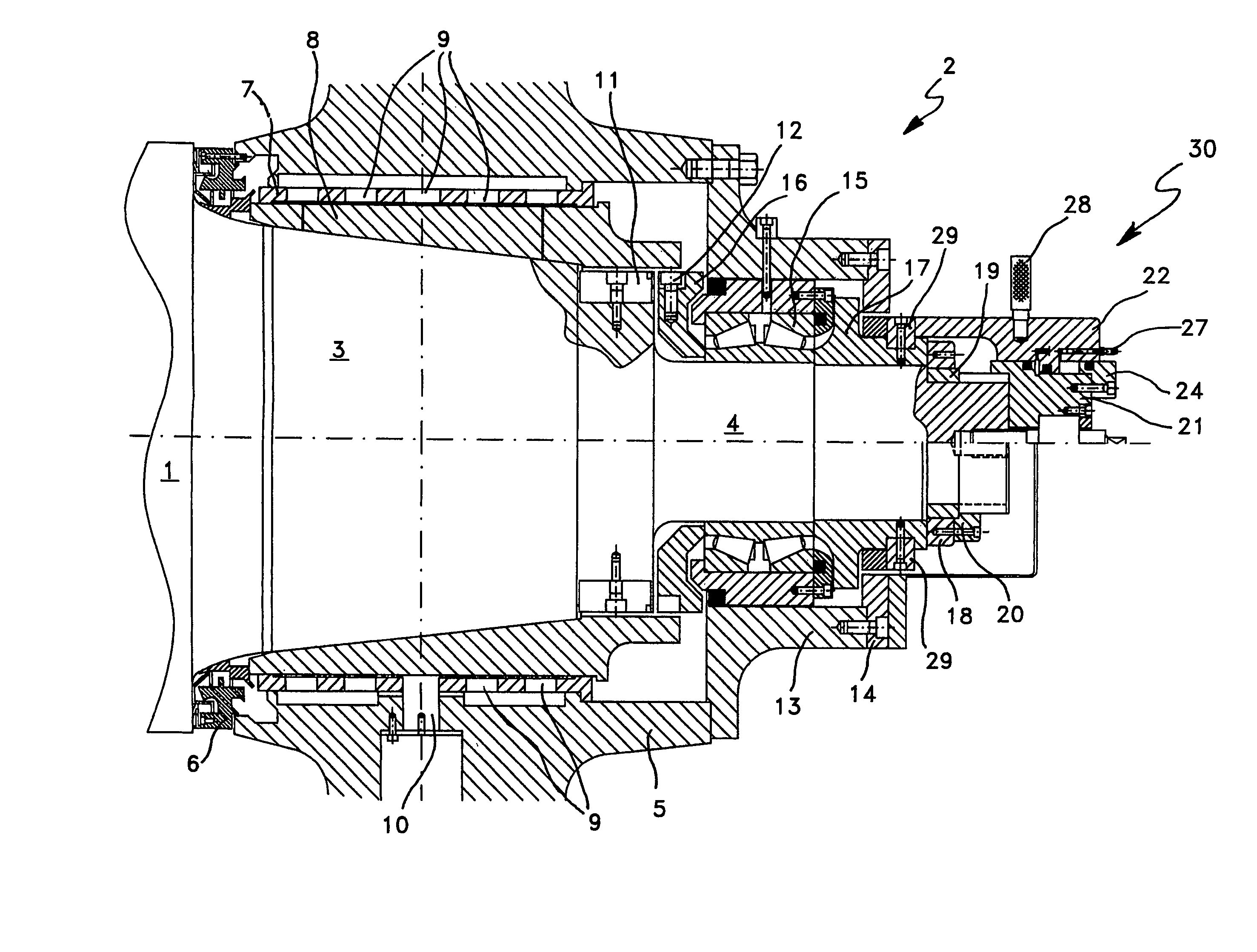
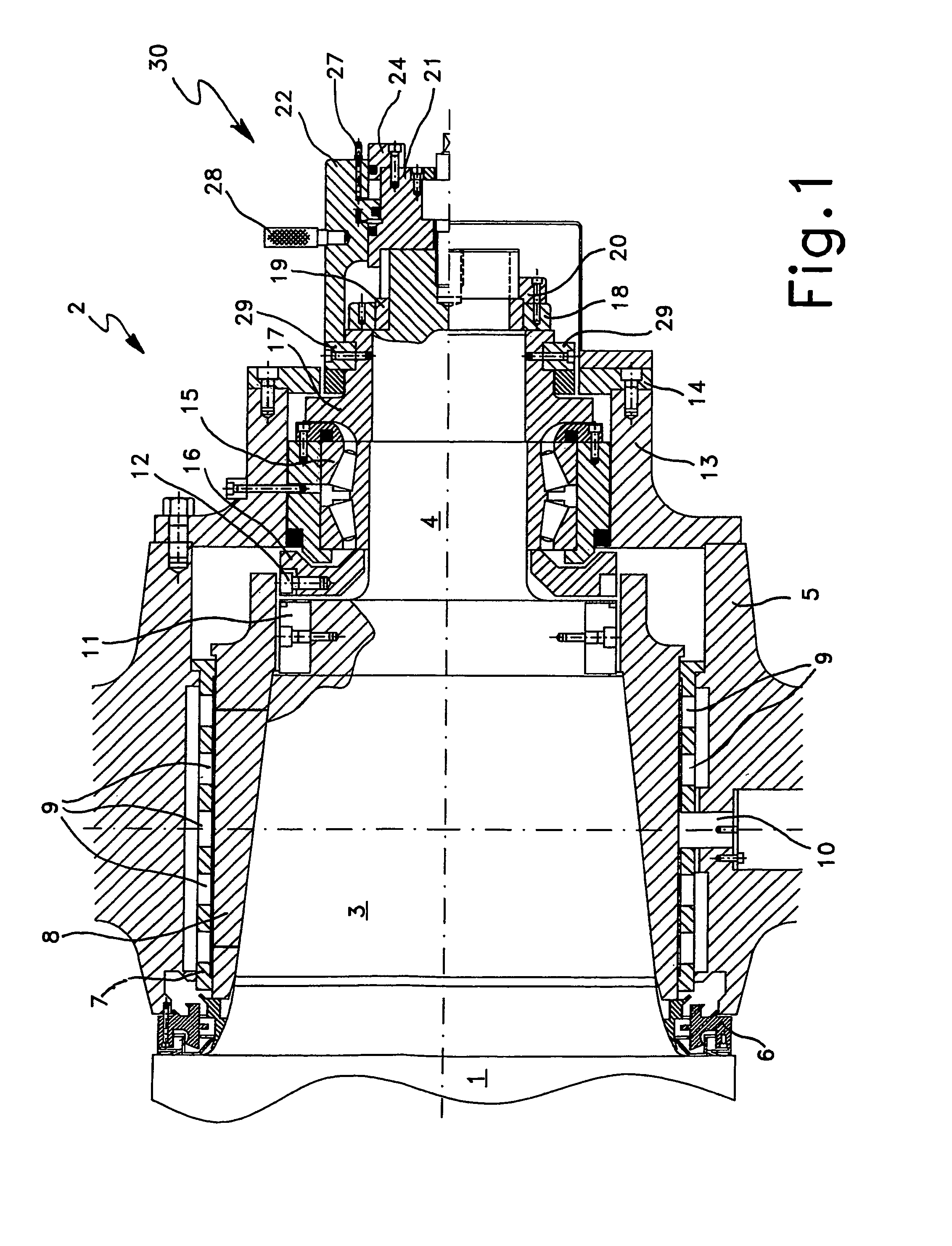
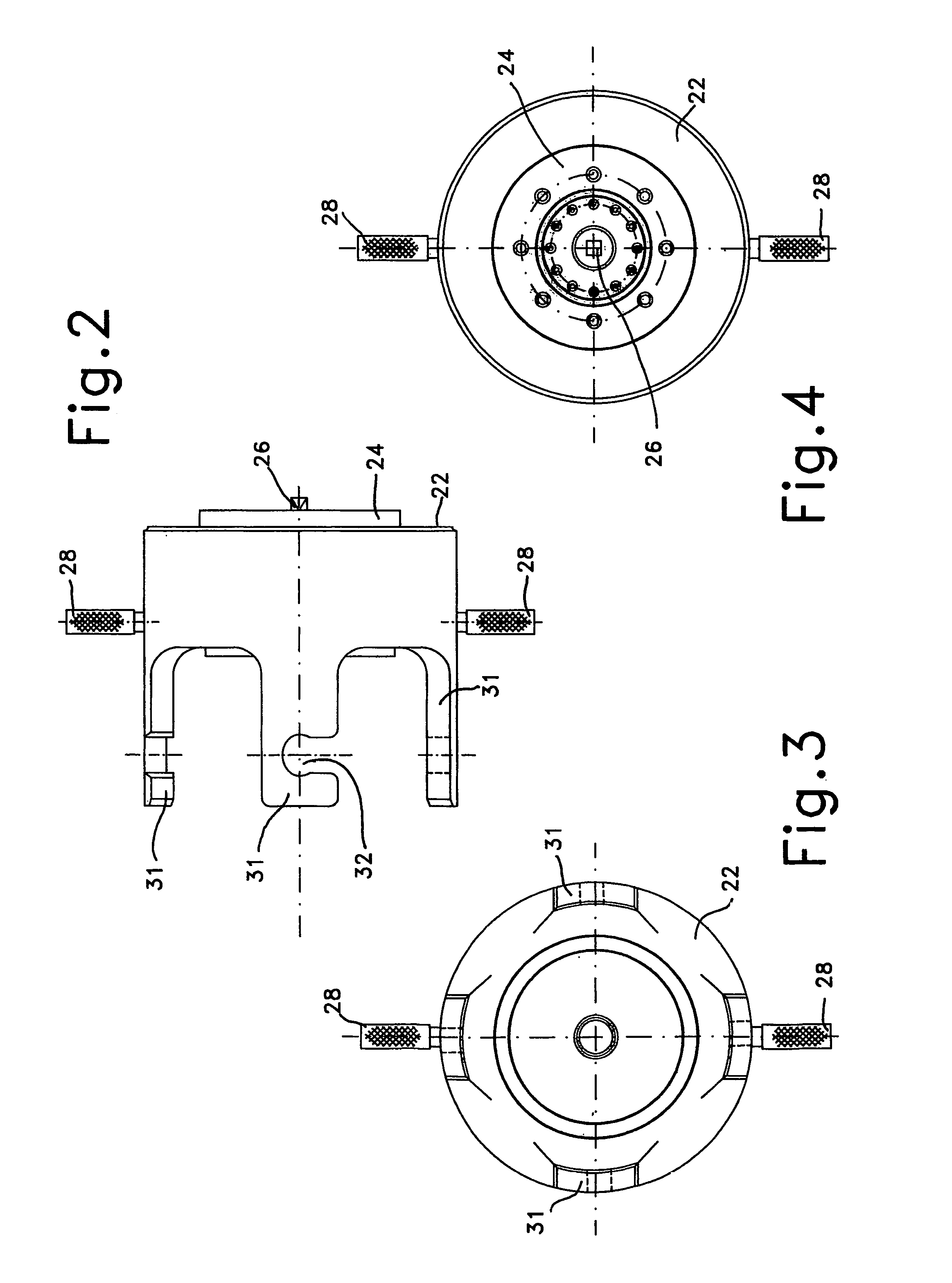
[0026]With particular reference to the invention, in the partial section above the axis of the bearing assembly, with reference to FIG. 1, the hydraulic locking and loosening device, globally designated by the reference numeral 30, is installed on the bearing assembly for carrying out the locking operation, and comprises a cylindrical body 21, surrounded by a ram 22. Both the body 21 and the ram 22 are made in such a way as to form between them two chambers of annular shape and to form a double-acting hydraulic actuator 23. A protective end cap 24 closes the hydraulic outer chamber of the actuator 23 formed in the space between the body 22 and the ram 21. The device 30 is fixed to the back-up roll body during the locking and loosening operation by means of a fixing screw 26. A quick-release coupling 27 enables connection to a hydraulic power source for actuating the device 30. The hydraulic locking device 30 is provided with two pin engagement levers 28 for facilitating twist-lock i...

second embodiment

[0031]With particular reference to the invention, illustrated in FIG. 7 and following figures, the hydraulic locking and loosening device, globally indicated by reference numeral 40, is installed on the bearing assembly for locking operation, and comprises a cylindrical body 41 surrounded by a ram 42. The body 41 and the ram 42 are designed in such a way as to provide two chambers of an annular shape, which constitute a double-acting hydraulic actuator 43. An end cap 44 closes the external hydraulic chamber of the actuator 43 formed by the space between the body 42 and the ram 41.

[0032]The device 40 is fixed to the back-up roll body during the locking or loosening operation by a first twist-lock bayonet fast-block coupling. The first twist-lock bayonet device comprises a certain number of teeth 46 set on the body 41, which are adapted to engage in the annular groove 47 present on the end part of the roll 1. The first bayonet device is operated by aligning the teeth 46 with the splin...


PUM

PropertyMeasurementUnit
angleaaaaaaaaaa
angleaaaaaaaaaa
axial forceaaaaaaaaaa

Abstract

A hydraulic locking and loosening device (40) is set on the neck of a rolling-mill roll or back-up roll with a conical part (3) and a cylindrical part (4), and comprising an oil-film bearing (7, 8), a spacer ring (16), a thrust bearing (15), a thrust ring (17), and a threaded lock ring (18). The locking device (30) comprises a body (21) inserted at the centre in a ram (22) to form a hydraulic actuator with two annular chambers (23), longitudinal arms (31), on each of which is provided a C-shaped notch (32), and cover (24) for closing the hydraulic chambers (23). A variant of the hydraulic locking and loosening device (40) is provided with a bayonet device for its engaging on the roll end.

Description

[0001]This application claims priority to International Patent Application Serial No. PCT / EP02 / 09785 filed on 2 Sep. 2002, claiming priority to Italian Patent Application Serial No. MI12001A001859 filed on 4 Sep. 2001.FIELD OF THE INVENTION[0002]The present invention relates to a hydraulic fast locking and loosening device, which can be temporarily mounted on bearing assemblies that support in rotation the necks of rolls of rolling-mill, for tightening and loosening the chock of the roll neck, as well as to a method for use of said device.STATE OF THE ART[0003]In roll stands, and more in particular in back-up rolls, it is common practice to utilise hydraulically actuated or screw-actuated devices for axially locking rolling mill bearing assemblies in their positions on the roll necks.[0004]In known rolling mills, such locking devices are designed as integral parts of the bearing assemblies, thereby increasing considerably the cost of said assemblies.[0005]A further drawback of screw...

Claims


Application Information

Patent Timeline
Patent Type & Authority Patents(United States)
IPC IPC(8): B21D53/10B21K1/76B23P17/00B21B31/07B21B31/08F16C13/02F16C35/02
CPCB21B31/074B21B31/08F16C13/02F16C35/02B21B2203/30Y10T403/7007Y10T29/53104Y10T29/5383Y10T29/49696Y10T29/49822F16C21/00F16C35/00F16C2322/12
Inventor DI GIACOMO, MARCO
Owner DANIELI & C OFF MEC SPA
Why Eureka
Try Eureka