
Controlled extrication module for motor vehicle crash injured people

a technology for extricating modules and people, which is applied in medical science, non-surgical orthopedic devices, ambulance services, etc., can solve problems such as difficulty in performing rescue maneuvers, and achieve the effects of avoiding any risk of further spinal injuries, shortening breath, and accentuated hypoxia of patients

Inactive Publication Date: 2008-06-17
LAMON MARCELO FERNANDO +2
View PDF8 Cites 4 Cited by
  • Summary
  • Abstract
  • Description
  • Claims
  • Application Information

AI Technical Summary

Benefits of technology

[0029]Under this circumstance, the victim's pathology, that is thorax injury, can be treated without any risk of further spinal injury since the patient's spine would be immobilized.
[0030]If as a result of using the present invention shortness of breath increases due to strap compression and the patient's hypoxia is accentuated, such risks are minimal as compared to medullar injury sequelae. Besides, it is reversible applying the proper treatment, that is pleural drainage, oxygen-therapy, etc.
[0033]Another purpose of the present invention is to keep the patient's spine safe during extrication and transportation of the patient by means of the extrication module, reducing the risk of further aggravating injuries when performing rescue and transport operations.
[0035]Also, another purpose of the present invention is to provide a secure means of handling to facilitate patient transportation to the rescue teams.

Problems solved by technology

The inventor has also taken into account the fact that in some vehicles, like those prepared for competition, rescue maneuvers are difficult to perform since competition vehicles usually have welded doors, side bars, and a safety cage for the driver and in some cases for a passenger.

Method used


Image

  • Controlled extrication module for motor vehicle crash injured people
  • Controlled extrication module for motor vehicle crash injured people
  • Controlled extrication module for motor vehicle crash injured people

Examples


Embodiment Construction

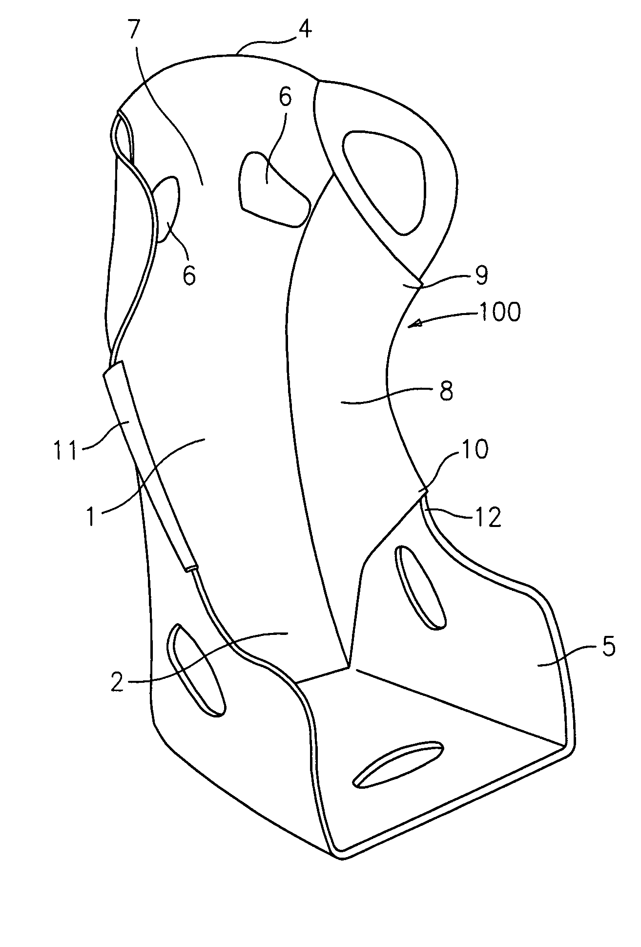
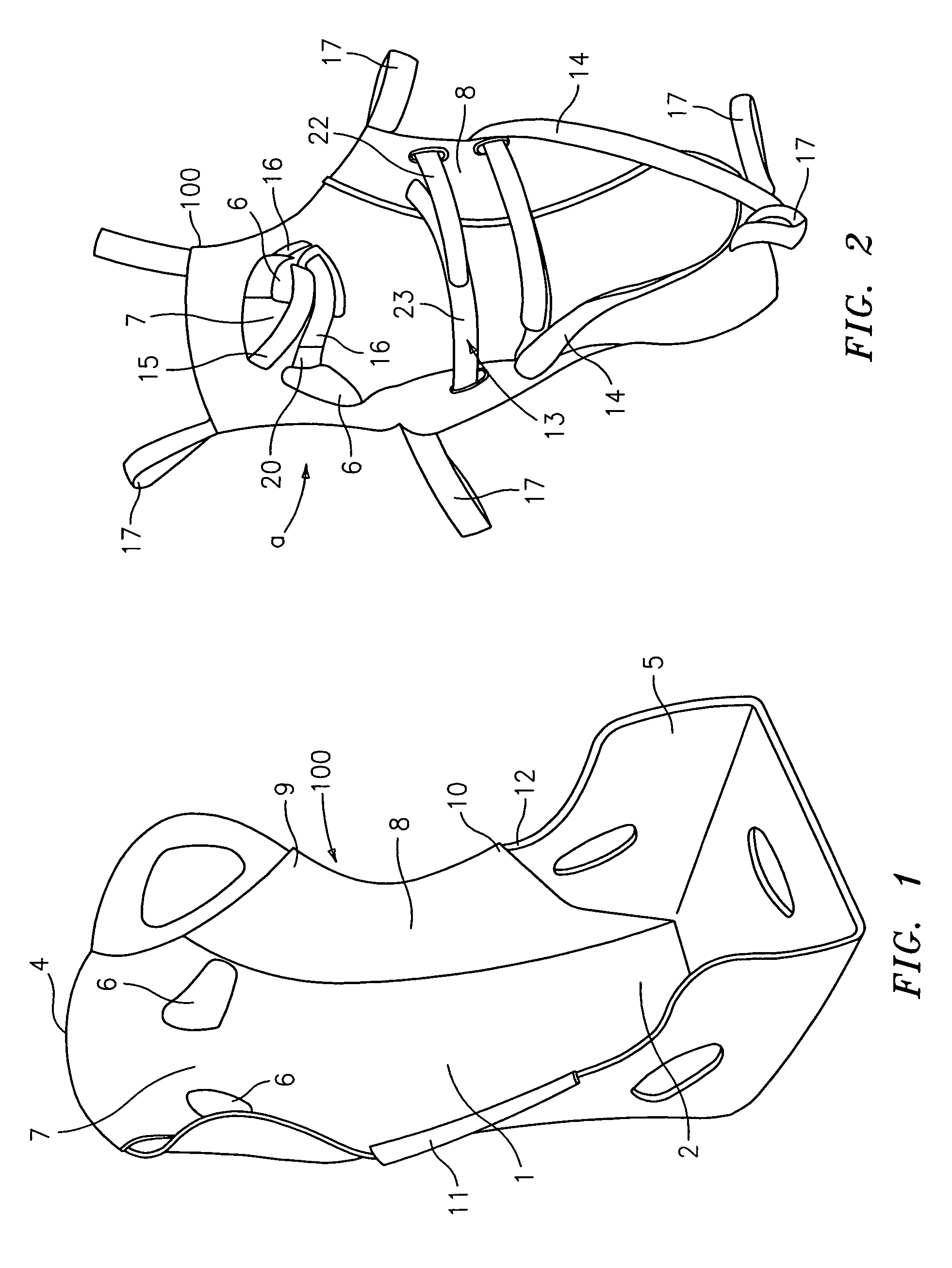
[0041]In the above described figures, the same reference numbers indicate equal or corresponding parts as follows: reference number (1) refers to a middle zone of the extrication module (100); reference number (2) refers to a lower zone of the extrication module (100); reference number (3) refers to an upper zone of the extrication module (100) and reference number (4) refers to a rounded edge of the extrication module (100).

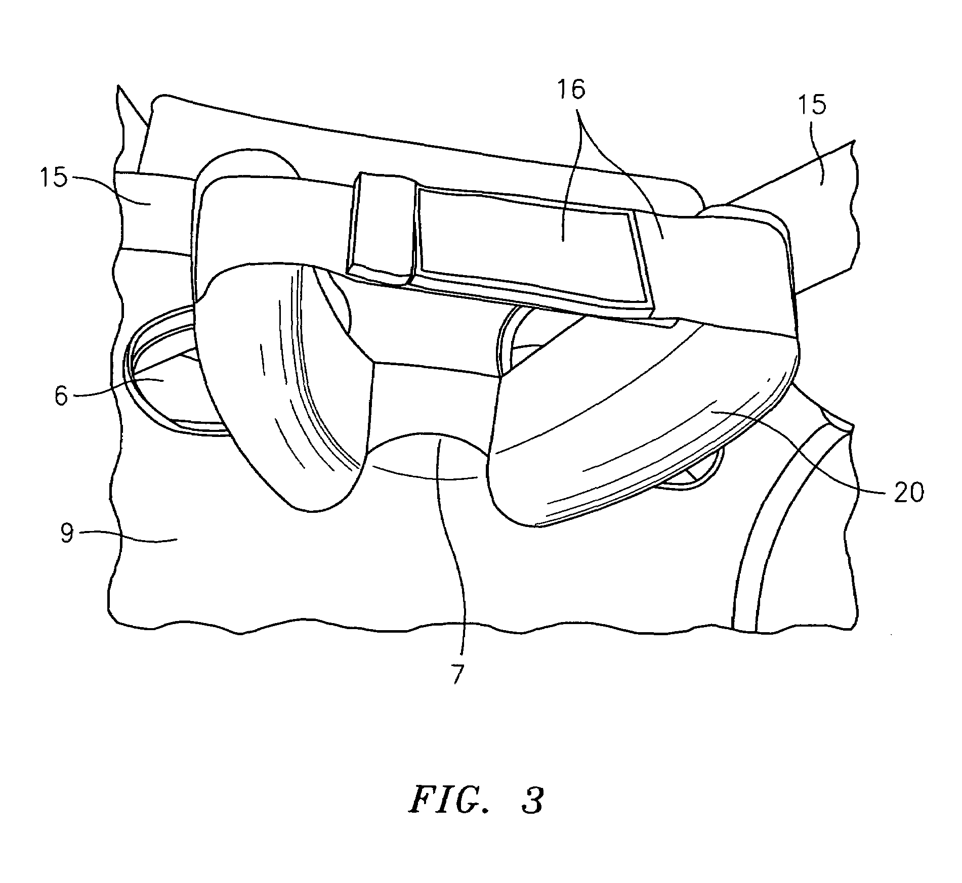
[0042]Reference number (5) indicates a seat on which the extrication module (100) is positioned. Reference number (6) indicates a pair of cavities in the extrication module (100). Reference number (7) indicates a center help associated with a cervical collar (20). Reference number (8) indicates a side aid.

[0043]Reference number (9) indicates an upper projection of the extrication module (100). Reference number (10) indicates a lower projection of the extrication module (100). Reference number (11) is a side border of the extrication module and reference number (...


PUM


Abstract

A controlled extrication module for the injured composed of a body with several means of immobilization of an injured person and supplied with devices for handling, maneuvering and transporting. The module is composed of a rigid plaque that provides a rear part with a medium zone coinciding with a person's back, a lower zone coinciding with a sacrococcygeal zone, and an upper zone coinciding with neck and head. The upper zone has a rounded edge which coincides with a cranial base and a border enabling attachment to an upper end of a seat. The upper zone also has two cavities for placing cervical collar straps which delimit a central help and semi-rigid fins connected to additional straps which attach at their ends. Both sides of the medium zone have upper and lower projections and an intermediate space supplying a side border. The border is placed on a side edge of the seat. The module also has a harness made up of upper and lower strips. The plaque lower zone is provided with two belts and a number of hand-holds.

Description

BACKGROUND OF THE INVENTION[0001]This invention consists of a controlled extrication module for people injured in motor vehicle crashes.[0002]In order to understand this invention so that it can be easily put into practice, a detailed description of the recommended implementation and drawings will be given in the following paragraphs. The description purpose is purely demonstrative and does not set limits to the invention itself whose components could be selected among several equivalents without neglecting the invention principles stated in this documentation.[0003]One of the main problems in motor vehicle crashes is removing the injured trapped inside the vehicle.[0004]This situation gets worse when people trying to help do not have first aid training.[0005]In fact, people trying to assist the victims in a vehicle crash frequently cause more severe injuries than the ones they are trying to reduce.[0006]Reduced reaction time when accelerating and stopping modern vehicles give the u...

Claims


Application Information

Patent Timeline
Patent Type & Authority Patents(United States)
IPC IPC(8): A61F5/37A61F5/058
CPCA61F5/05883A61G1/06
Inventor LAMON, MARCELO FERNANDOLASCANO GARZON, AGUSTINALIAGA PAZ, ERNESTO
Owner LAMON MARCELO FERNANDO
Learn More