Droplet ejection apparatus and a method of detecting and judging head failure in the same

a technology of droplet ejection and head failure, which is applied in the direction of printing, other printing apparatus, etc., can solve the problems of blockage of nozzles, deterioration of image quality, and inability of nozzles to eject ink droplets

Active Publication Date: 2008-06-17
SEIKO EPSON CORP
View PDF81 Cites 12 Cited by
  • Summary
  • Abstract
  • Description
  • Claims
  • Application Information

AI Technical Summary

Benefits of technology

[0022]Therefore, according to the droplet ejection apparatus of the invention, in comparison with the conventional droplet ejection apparatus capable of detecting an ejection failure, the droplet ejection apparatus of the invention does not need other parts (for example, optical missing dot detecting device or the like). As a result, not only an ejection failure (including a head failure, “head failure” will be described later) of the droplets can be detected without increasing the size of the droplet ejection head, but also the manufacturing costs of the droplet ejection apparatus capable of carrying out an ejection failure (missing dot) detecting operation can be reduced. In addition, because the droplet ejection apparatus of the invention detects an ejection failure of the droplets through the use of the residual vibration of the diaphragm after the droplet ejection operation, an ejection failure of the droplets can be detected even during the recording operation.
[0034]According to the droplet ejection apparatus in another embodiment of the invention, in place of the residual vibration of the diaphragm described above, by detecting the residual vibration of the electromotive voltage generated from the actuator, it is possible to achieve the operation and effect similar to the droplet ejection apparatus in one embodiment described above. In this way, the droplet ejection apparatus of the invention can adopt the similar structure using the electromotive voltage of the piezoelectric actuator.
[0037]It is preferable that the droplet ejection apparatus of the invention further includes a temperature sensor for measuring ambient temperature of the plurality of droplet ejection heads. In this case, it is preferable that the predetermined reference value is corrected on the basis of the ambient temperature measured by the temperature sensor. This makes it possible to detect the head failure in the droplet ejection heads more accurately.

Problems solved by technology

However, there is a case where some of the nozzles are blocked due to an increase of ink viscosity, intrusion of air bubbles, adhesion of dust or paper dust, or the like, and therefore these nozzles become unable to eject ink droplets.
When the nozzles are blocked, missing dots occur within a printed image, which results in deterioration of image quality.
Hence, this detecting method generally has a problem that the light source and the optical sensor have to be set (or provided) with exact accuracy (high degree of accuracy) so that droplets ejected through the nozzles of the droplet ejection head (ink jet head) pass through a space between the light source and the optical sensor and therefore intercept light from the light source to the optical sensor.
In addition, since such a detector is generally expensive, the droplet ejection apparatus having the detector has another problem that the manufacturing costs of the ink jet printer are increased.
Further, since an output portion of the light source or a detection portion of the optical sensor may be smeared by ink mist through the nozzles or paper dust from printing sheets or the like, there is a possibility that the reliability of the detector becomes a matter of concern.
Further, although the optical missing dot detecting method described above can detect the missing dot, that is, an ejection failure (non-ejection) of ink droplets from the nozzles, the cause of the missing dot (ejection failure) cannot be identified (judged) on the basis of the detection result.
Hence, there is another problem that it is impossible to select and carry out appropriate recovery processing depending on the cause of the missing dot (ejection failure).
This increases discharged ink (wasted ink), or causes several types of recovery processing to be carried out because appropriate recovery processing is not carried out, and thereby reduces or deteriorates throughput of the ink jet printer (droplet ejection apparatus).

Method used


Image

  • Droplet ejection apparatus and a method of detecting and judging head failure in the same
  • Droplet ejection apparatus and a method of detecting and judging head failure in the same
  • Droplet ejection apparatus and a method of detecting and judging head failure in the same

Examples


first embodiment

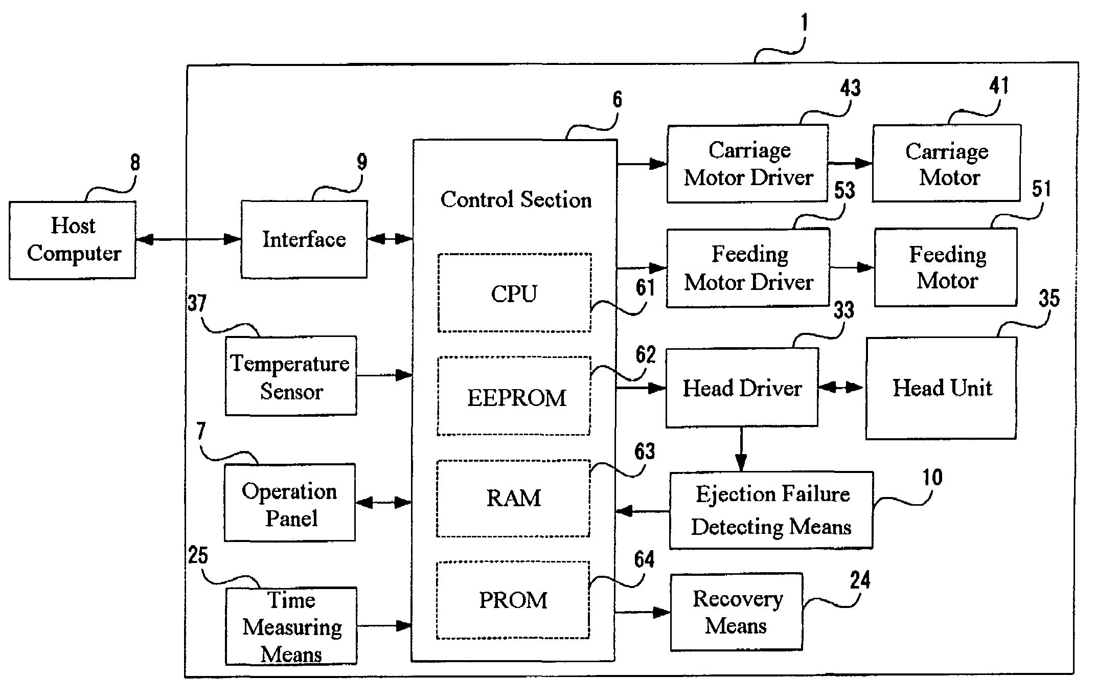
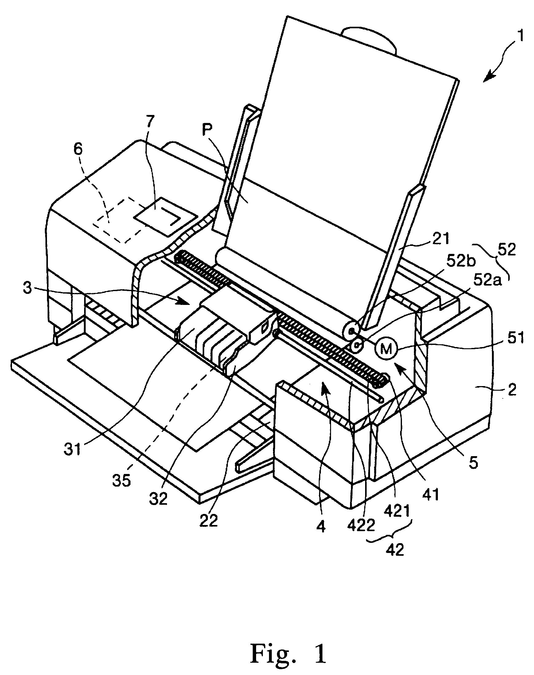
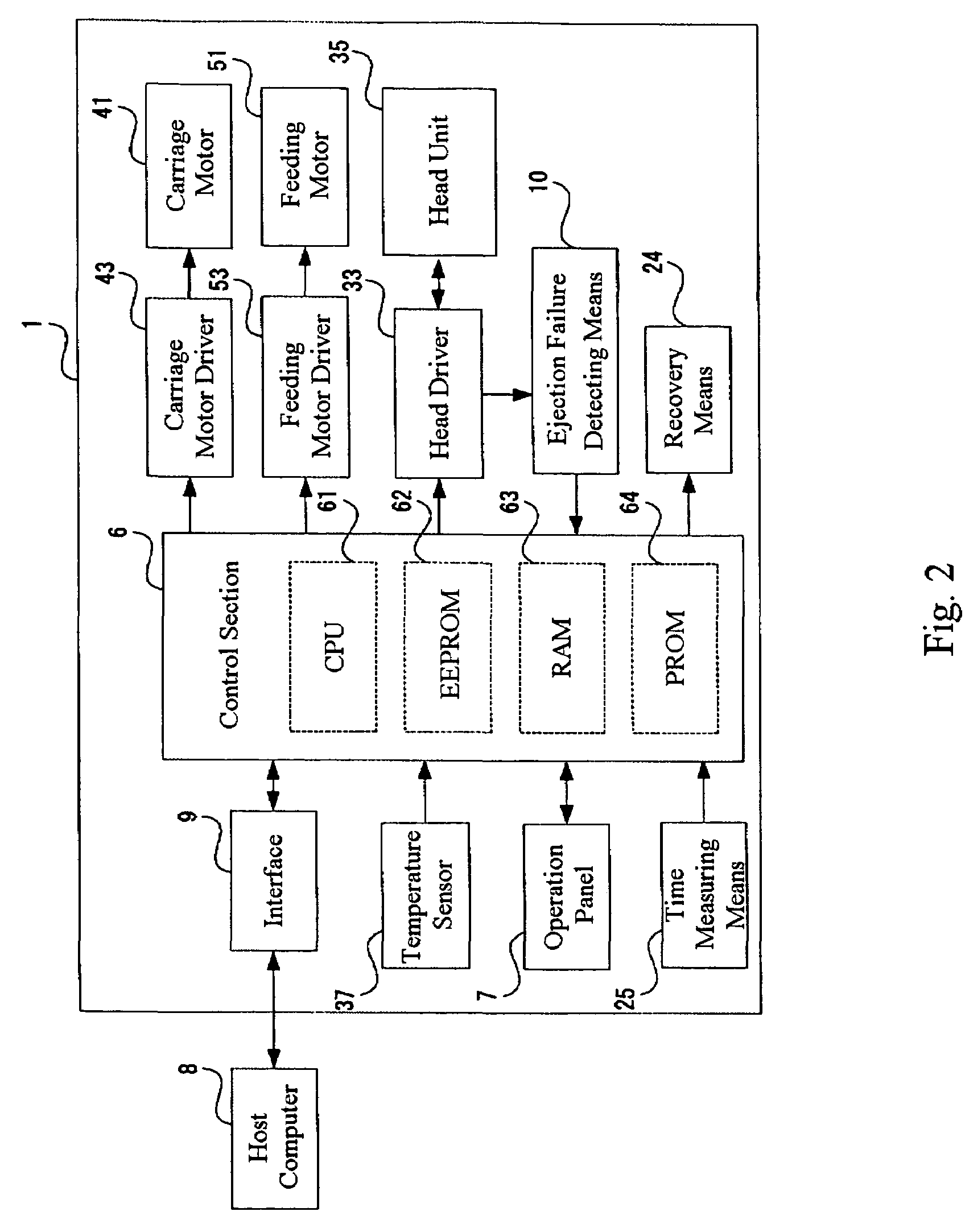
[0124]FIG. 1 is a schematic view showing the configuration of an ink jet printer 1 as one type of droplet ejection apparatus according to a first embodiment of the invention. Now, in following explanations using FIG. 1, an upper side and lower side are referred to as “upper” and “lower,” respectively. First, the configuration of the ink jet printer 1 will be described.

[0125]The ink jet printer 1 shown in FIG. 1 includes a main body 2. A tray 21 on which recording sheets P may be placed, a sheet discharge port 22, through which the recording sheet P is discharged, and an operation panel 7 are respectively provided in the rear of the top, in the front of the bottom, and on the top surface, of the main body 2.

[0126]The operation panel 7 is provided with a display portion (not shown) for displaying an error message or the like, such as a liquid crystal display, an organic EL display, an LED lamp or the like, and an operation portion (not shown) comprising various kinds of switches or th...

second embodiment

[0359]Examples of other configurations of the ink jet head of the invention will now be described. FIGS. 51-54 are cross sectional views each schematically showing an example of other configuration of the ink jet head (head unit). Hereinafter, an explanation will be given with reference to these drawings; however, differences from the first embodiment described above are chiefly described, and the description of the similar portions is omitted.

[0360]An ink jet head 100A shown in FIG. 51 is one that ejects ink (liquid material) within a cavity 208 through a nozzle 203 as a diaphragm 212 vibrates when a piezoelectric element 200 is driven. A metal plate 204 made of stainless steel is bonded to a nozzle plate 202 made of stainless steel in which the nozzle (hole) 203 is formed, via an adhesive film 205, and another metal plate 204 made of stainless steel is further bonded to the first-mentioned metal plate 204 via an adhesive film 205. Furthermore, a communication port forming plate 20...


PUM


Abstract

It is an object of the invention to provide a droplet ejection apparatus and a method of detecting and judging a head failure that can detect an ejection failure and carry out appropriate recovery processing according to a cause thereof. The droplet ejection apparatus of the invention includes a plurality of droplet ejection heads, each of the droplet ejection heads including a diaphragm and an actuator which displaces the diaphragm; a driving circuit which drives the actuator of each droplet ejection head; residual vibration detecting means 16 for detecting a residual vibration of the diaphragm displaced by the actuator after the actuator has been driven by the driving circuit; pulse generating means for generating reference pulses; computation means 17 for carrying out a computation for the number of reference pulses generated by the pulse generating means on the basis of the residual vibration of the diaphragm detected by the residual vibration detecting means; time measuring means for measuring a lapsed time since the actuator has been driven by the driving circuit; and head failure judging means 20 for judging a head failure in the droplet ejection heads on the basis of the computation result of the computation means 17 and the lapsed time measured by the time measuring means.

Description

BACKGROUND OF THE INVENTION[0001]1. Technical Field[0002]The present invention relates to a droplet ejection apparatus and a method of detecting and judging a head failure.[0003]2. Background Art[0004]An ink jet printer, which is one type of droplet ejection apparatus, forms an image on a predetermined sheet of paper by ejecting ink drops (droplets) via a plurality of nozzles of a printing head of the ink jet printer. The printing head (ink jet head) of the ink jet printer is provided with a number of nozzles. However, there is a case where some of the nozzles are blocked due to an increase of ink viscosity, intrusion of air bubbles, adhesion of dust or paper dust, or the like, and therefore these nozzles become unable to eject ink droplets. When the nozzles are blocked, missing dots occur within a printed image, which results in deterioration of image quality.[0005]As far, a method of optically detecting a state where no ink droplets are ejected through the nozzles of the ink jet h...

Claims


Application Information

Patent Timeline
Patent Type & Authority Patents(United States)
IPC IPC(8): B41J2/01B41J2/175B41J2/045B41J2/055B41J2/165
CPCB41J2/16579B41J2002/14354
Inventor SHINKAWA, OSAMUSAKAGAMI, YUSUKETAJIMA, KOKI
Owner SEIKO EPSON CORP
Why Eureka
Try Eureka