Surgical microscope

a surgical microscope and microscope technology, applied in the field of surgical microscopes, can solve the problems of extremely cumbersome utilization of retinal diagnostic devices, difficult implementation of difficulty in directing observation beam paths through the patient's pupil

Inactive Publication Date: 2008-06-17
LEICA INSTR SINGAPORE PTE
View PDF11 Cites 39 Cited by
  • Summary
  • Abstract
  • Description
  • Claims
  • Application Information

AI Technical Summary

Benefits of technology

[0011]From these desires and from the disadvantages that presently exist, there arises the object upon which the invention is based, that of creating an improved surgical microscope that, while it is being used, permits the making of a diagnosis as in the case of a retinal diagnostic device, with no need to remove the surgical microscope from the operating position.

Problems solved by technology

Guidance of the observation and illumination beam paths together through the patient's pupil is, however, very difficult to implement.
The reason is that utilization of the retinal diagnostic device is extremely cumbersome, since surgery using the surgical microscope must be interrupted in order to move the retinal diagnostic device over the patient's eye in order to make the desired (interim) diagnosis.

Method used


Image

  • Surgical microscope
  • Surgical microscope
  • Surgical microscope

Examples


Embodiment Construction

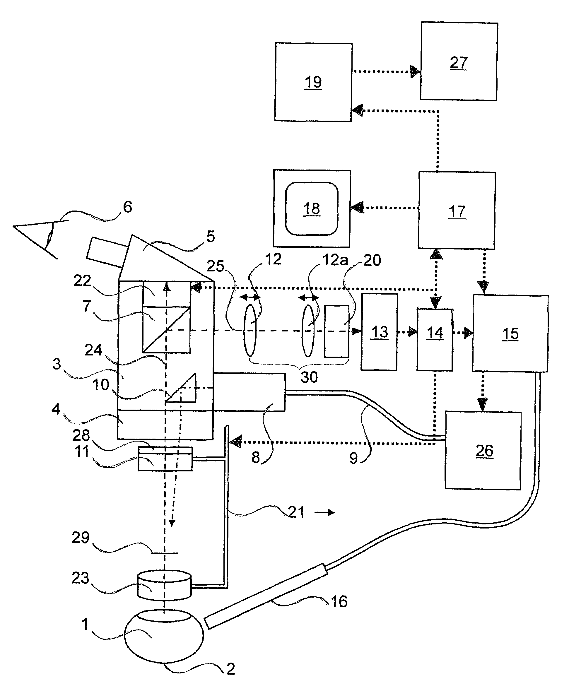
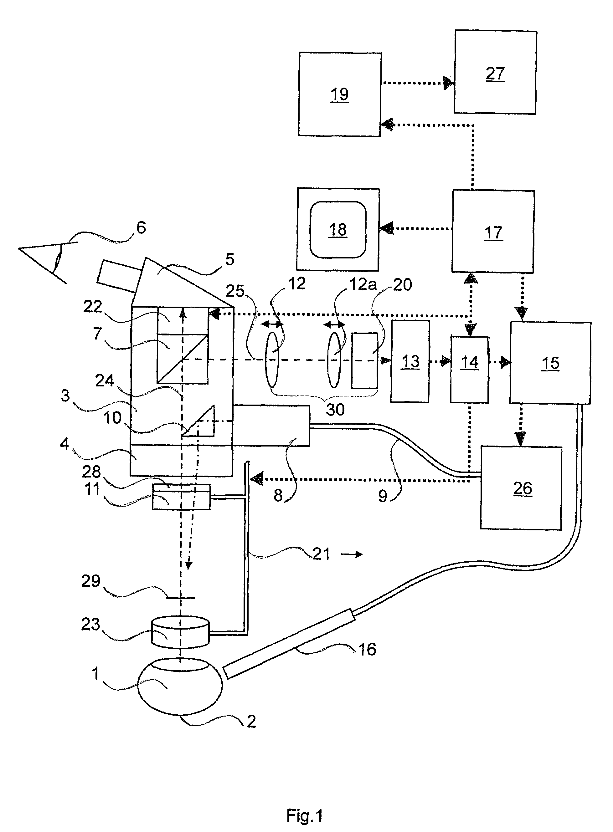
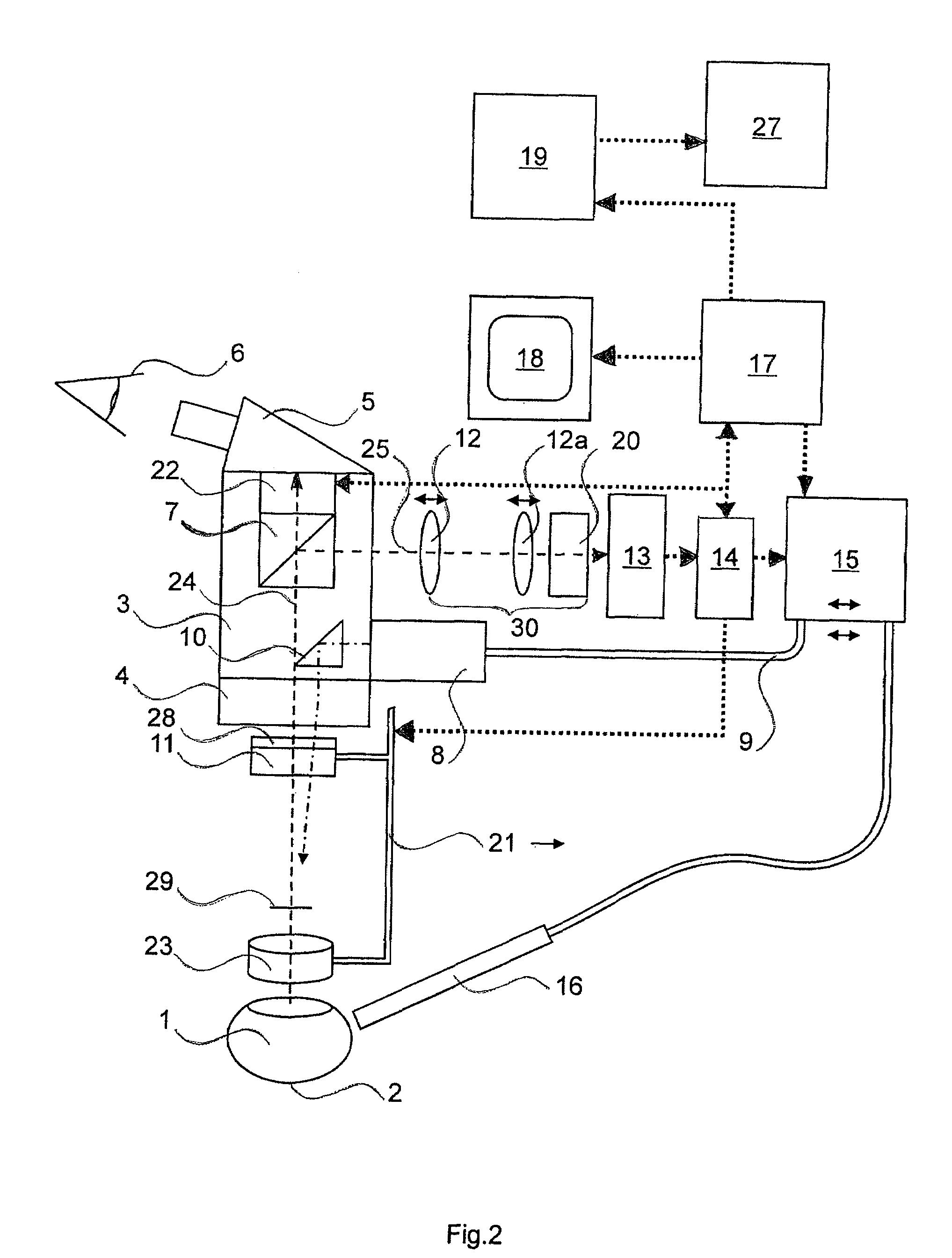
[0019]As is evident from FIG. 1, the inventive idea encompasses the fact that the retinal diagnostic device comprises a first component 13 and a second component 23. A surgical microscope 3 is incorporated between first component 13 and second component 23. In addition, a camera beam path 25 is coupled out of an observation beam path 24 by means of a beam splitter 7, as is usual, for example and in a manner known per se, for photographic or video documentation. After beam splitter 7, camera beam path 25 is directed through imaging lenses 12, 12a (lens groups can also be used instead of individual lenses) and through a deflection element 20 to a digital camera 13. Deflection element 20 that is depicted represents one possible optical deflection system and can comprise mirrors and / or prisms, and generates a rightreading and upright image on the image sensor of camera 13. The image sensor of camera 13 is typically an array of light sensitive pixels, for example a CCD array.

[0020]The im...


PUM


Abstract

The invention concerns a combined surgical microscope system having a surgical microscope and a retinal diagnostic device of modified configuration having transscleral pulsed illumination.

Description

CROSS REFERENCE TO RELATED APPLICATIONS[0001]This application claims priority of the German patent application 103 02 401.8 which is incorporated by reference herein.FIELD OF THE INVENTION[0002]The invention concerns a surgical microscope having a beam path for a camera.BACKGROUND OF THE INVENTION[0003]With known surgical microscopes, for example with the M841 of the Leica company (see brochure, “The Leica M841—The Ultimate Surgical Microscope System for Ophthalmology,” Publication no. 10 M1 841 Oen, printed VII.2000), surgery is performed on and below the retina (fundus) when ophthalmological diseases are present. The region extends from the macula to the ora serrata.[0004]There also exist retinal diagnostic devices specifically for this sector, for example the retinal diagnostic device of Medibell Medical Vision Technologies Ltd., Haifa, Israel, referred to (in a brochure without publication information) as the “Panoret 1000—Wide-Angle Digital Retinal Camera.” Retinal diagnostic d...

Claims


Application Information

Patent Timeline
Patent Type & Authority Patents(United States)
IPC IPC(8): A61B3/14A61B3/10A61B3/12A61B19/00G02B21/00G02B21/06G02B21/36
CPCG02B21/0012G02B21/361G02B21/365A61B3/13
Inventor SANDER, ULRICH
Owner LEICA INSTR SINGAPORE PTE
Why Eureka
Try Eureka