Apparatus and method for analyzing relative outward flow characterizations of fabricated features

a technology of fabricated features and apparatus, which is applied in the field of manufacturing gas turbine engine components, can solve the problems of gas turbine engines, difficult manufacturing, and high temperature and high velocity gases, and achieve the effects of accurate and rapid determination of flow characteristics, easy interpretation, and more error-fr

Inactive Publication Date: 2008-06-17
MEYER TOOL
View PDF18 Cites 26 Cited by
  • Summary
  • Abstract
  • Description
  • Claims
  • Application Information

AI Technical Summary

Benefits of technology

[0008]The present invention provides an inspection apparatus and process that accurately and quickly determine the flow characteristics of cooling features fabricated in gas turbine blades. With the inspection apparatus and process of the present invention, the flow characteristics are easy to interpret; and thus, the inspection apparatus and process are faster, more error-free and less expensive than known tactile and visual inspection processes. The inspection apparatus of the present invention provides an automatic process and thus, removes the chance of human error. Therefore, the inspection apparatus of the present invention is especially useful for inspecting a presence and quality of a large number of complex cooling holes in gas turbine component.

Problems solved by technology

During operation, gas turbine engines, whether used for flight or stationary power generation, develop extremely high temperature and high velocity gases in a combustor portion of the engine.
High quality cooling holes 22 with diffusers 30 provide superior performance but are costly and difficult to manufacture.
As can be appreciated, such an inspection process is highly repetitive, tedious and stressful for the inspector and, in addition, is expensive and inefficient for the manufacturer of the turbine component.
These methods need a human visual check or physical measurement of a single feature to characterize its flow condition, All of these known methods are time-consuming and rely on human intervention to perform the characterization which leads to errors.

Method used


Image

  • Apparatus and method for analyzing relative outward flow characterizations of fabricated features
  • Apparatus and method for analyzing relative outward flow characterizations of fabricated features
  • Apparatus and method for analyzing relative outward flow characterizations of fabricated features

Examples


Embodiment Construction

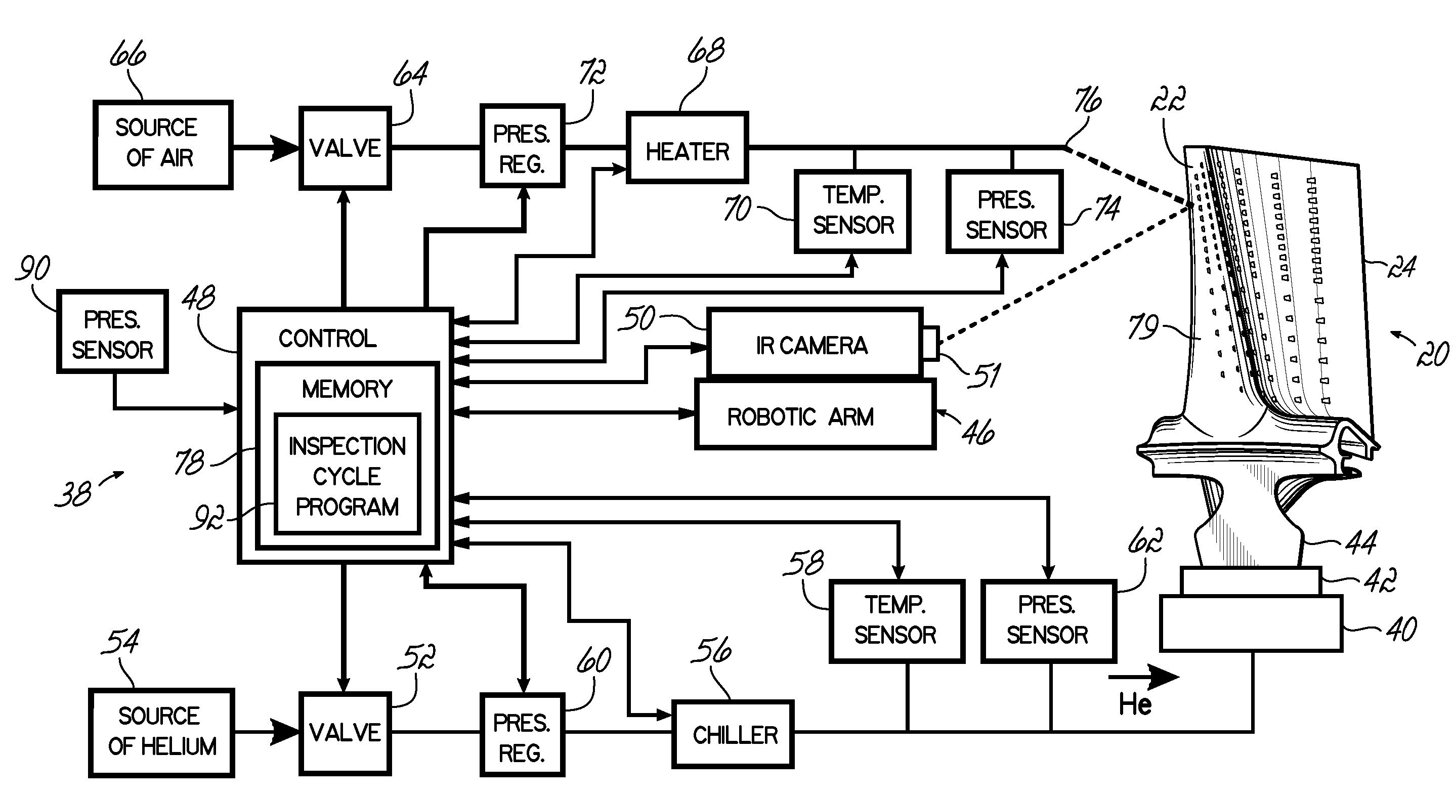
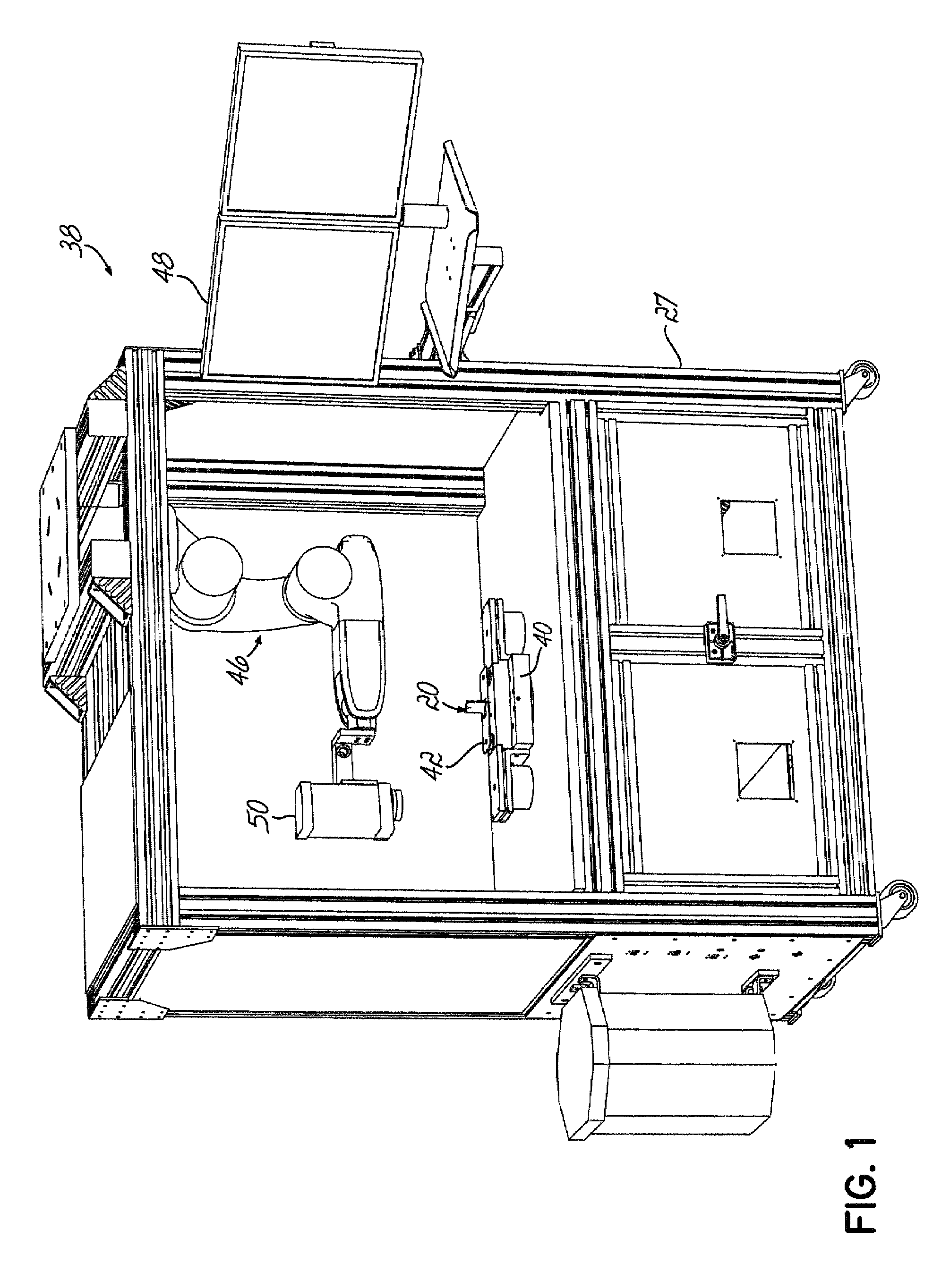
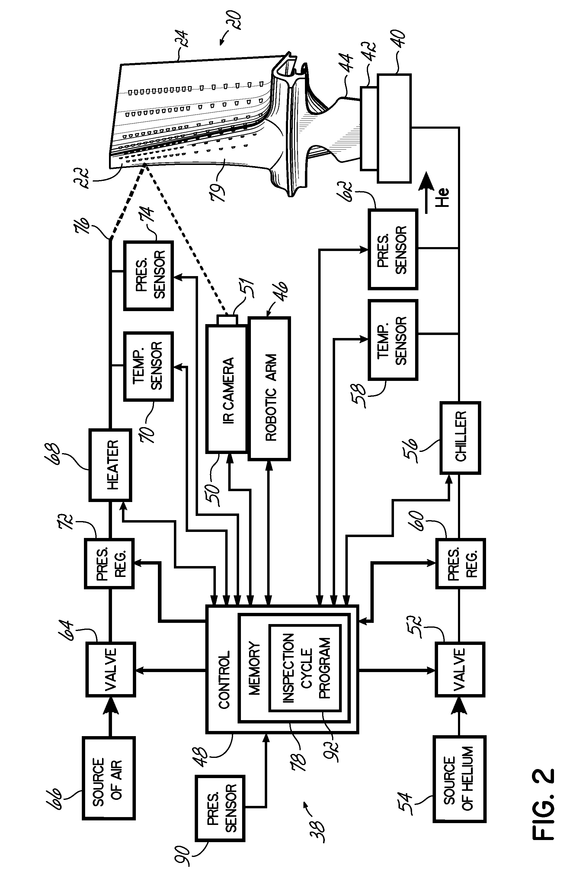
[0020]Referring to FIGS. 1 and 2, one example of a feature inspection system 38 is used to inspect fabricated features in a part, for example, air cooling holes 22 in a known turbine blade 20 as described with respect to FIGS. 8 and 9. The blade 20 is supported in a holding fixture 40; and a gas tight seal 42, for example, a molded urethane seal, is formed around an inlet opening at a base 44 of the blade 20. A robotic arm 46 is mounted in a cabinet 27 and is controlled by a programmable control 48 also mounted on the cabinet 27. The robotic arm 46 is operable to position an infrared (IR) radiometer or camera 50 with respect to the blade 20. In one exemplary embodiment, the robotic arm 46 is mounted upside-down above the blade 20, so that the robotic arm 46 can be moved to different positions and orientations that permit the IR camera 50 to provide thermal images of all of the fabricated blade features 22 to be inspected. The robotic arm 46 may be one of several commercially availab...


PUM


Abstract

An apparatus and method for characterizing gas flow through features fabricated in a hollow part. A pressurized gas is applied to an interior of the part, and this gas pressure flows outward through features fabricated in the part. At the same time, a stabilizing pressurized gas is applied to an exterior part skin; and the stabilizing gas has a controlled temperature differential from the gas applied to the part interior. An infrared signature of escaping gas and the surrounding part skin is analyzed by a classification method. Analysis of this infrared signature classifies the relative flow rate, size and position of the feature fabricated in the part.

Description

FIELD OF THE INVENTION[0001]The present invention relates to manufacturing gas turbine engine components and, more particularly, to inspecting complex cooling holes through a surface of a gas turbine engine component.BACKGROUND OF THE INVENTION[0002]During operation, gas turbine engines, whether used for flight or stationary power generation, develop extremely high temperature and high velocity gases in a combustor portion of the engine. These gases are ducted on blades of a turbine rotor to cause rotation of the rotor and are redirected by the stator vanes onto additional rotor blades to produce more work. Because of the high heat of the gases, it is desirable to cool the blades and vanes to prevent damage and, to extend the useful life of, these engine components. It is known in the art that a turbine component such as that shown in FIG. 8 can be cooled by film cooling that is provided by a plurality of fabricated features, for example, cooling holes.[0003]A commonly used method o...

Claims


Application Information

Patent Timeline
Patent Type & Authority Patents(United States)
IPC IPC(8): G01J5/02
CPCF01D5/141F01D21/003G01J2005/0077G01M3/002G01N25/72G06T7/0004G06T2207/30164
Inventor KEY, DOUGLAS E.EASTON, BEAU
Owner MEYER TOOL
Why Eureka
Try Eureka