Ball joint gimbal mirror with actuator assembly

a technology of actuators and gimbals, applied in the field of optics, can solve the problems of large physical dimensions of dual electro-optic scanners, one or more problems in each of these conventional scanning techniques,

Inactive Publication Date: 2008-06-17
BAE SYST INFORMATION & ELECTRONICS SYST INTERGRATION INC
View PDF9 Cites 55 Cited by
  • Summary
  • Abstract
  • Description
  • Claims
  • Application Information

AI Technical Summary

Benefits of technology

[0006]One embodiment of the present invention provides a scanning mechanism that includes a ball bearing integrally connected to a mirror assembly and a ball bearing socket that allows the ball bearing to rotate over an angle range (e.g., such as angles between 5 and 50 degree, or greater than 50 degrees). In addition, an actuator assembly is attached to the mirror assembly, for moving the mirror assembly in response to applied control signals. The scanning mechanism may further include control circuitry for providing the control signals. In one particular configuration, the actuator assembly includes a magnet-coil arrangement that is operatively coupled to the mirror assembly, that moves the mirror assembly in response to applied control signals. In one such case, the actuator assembly includes a donut-shaped coil, and a magnet attached to the mirror assembly, wherein the magnet moves within the coil in response to applied control signals, thereby moving the mirror assembly. The donut-shaped coil can be, for example, one of a plurality in a coil stack, and control signals can be sequentially applied to the coils in the stack thereby causing the magnet to move within the stack. In another such particular case, the actuator assembly has two to four of the coil stacks, each having a corresponding magnet that moves within its coil stack in response to applied control signals, thereby providing multi-axis scanning capability. In another such particular case, the actuator assembly includes four stacks of donut-shaped coils, and four magnets. Each magnet is flexibly attached to the mirror assembly, wherein each magnet moves within a corresponding coil stack in response to applied co...

Problems solved by technology

However, each of these conventional scanning techniques is associated with one or more problems.
Dual electro-optic sc...

Method used


Image

  • Ball joint gimbal mirror with actuator assembly
  • Ball joint gimbal mirror with actuator assembly
  • Ball joint gimbal mirror with actuator assembly

Examples


Embodiment Construction

[0015]Compact scanning techniques that can scan a large degree optical solid angle are disclosed.

[0016]General Overview

[0017]One particular embodiment is a processor controlled scanner that is capable of a large degree optical solid scan angle. Dual axis scan capability is provided with a single compact package (e.g., plastic or polymer package). Numerous applications can benefit from such a large angle compact optical scanner, such as countermeasure and tracking applications.

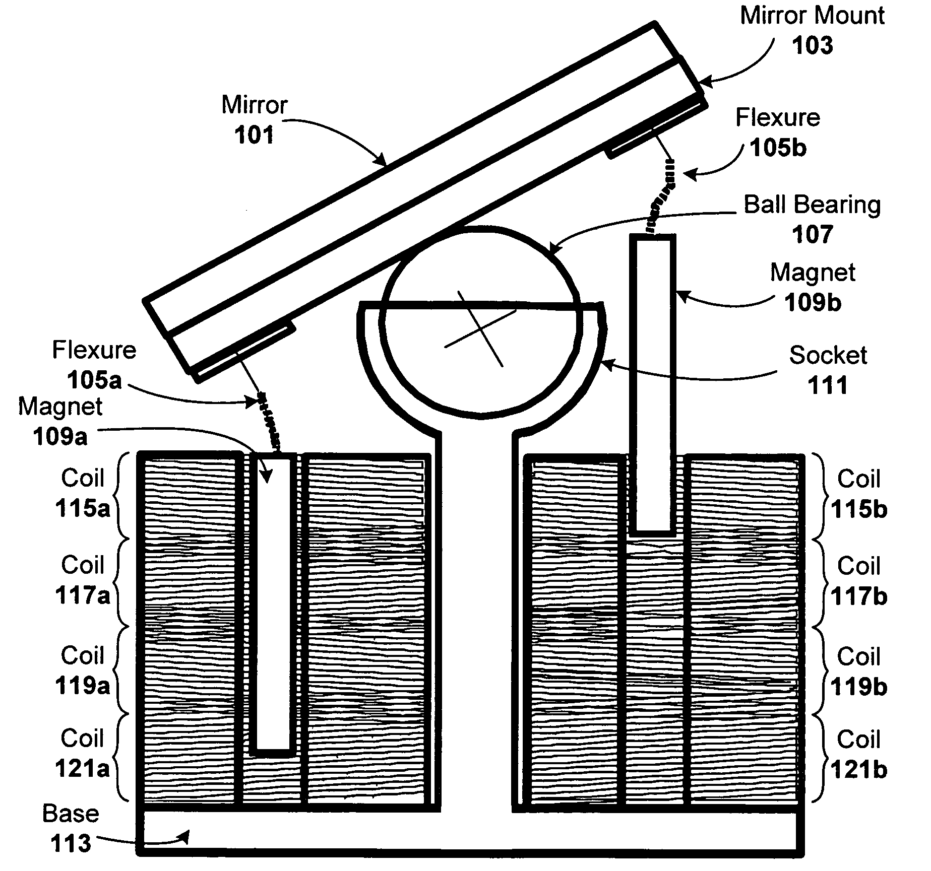
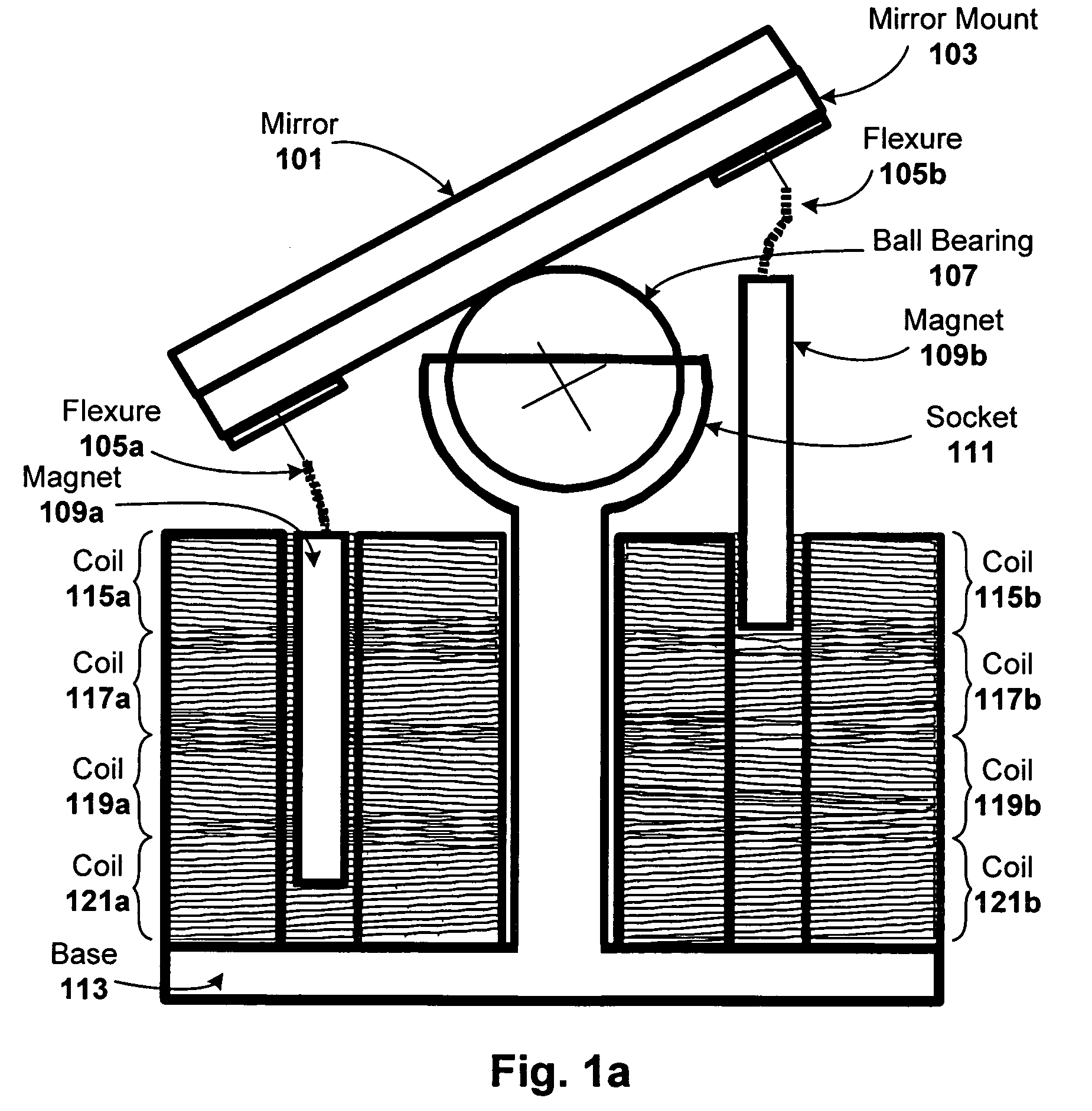
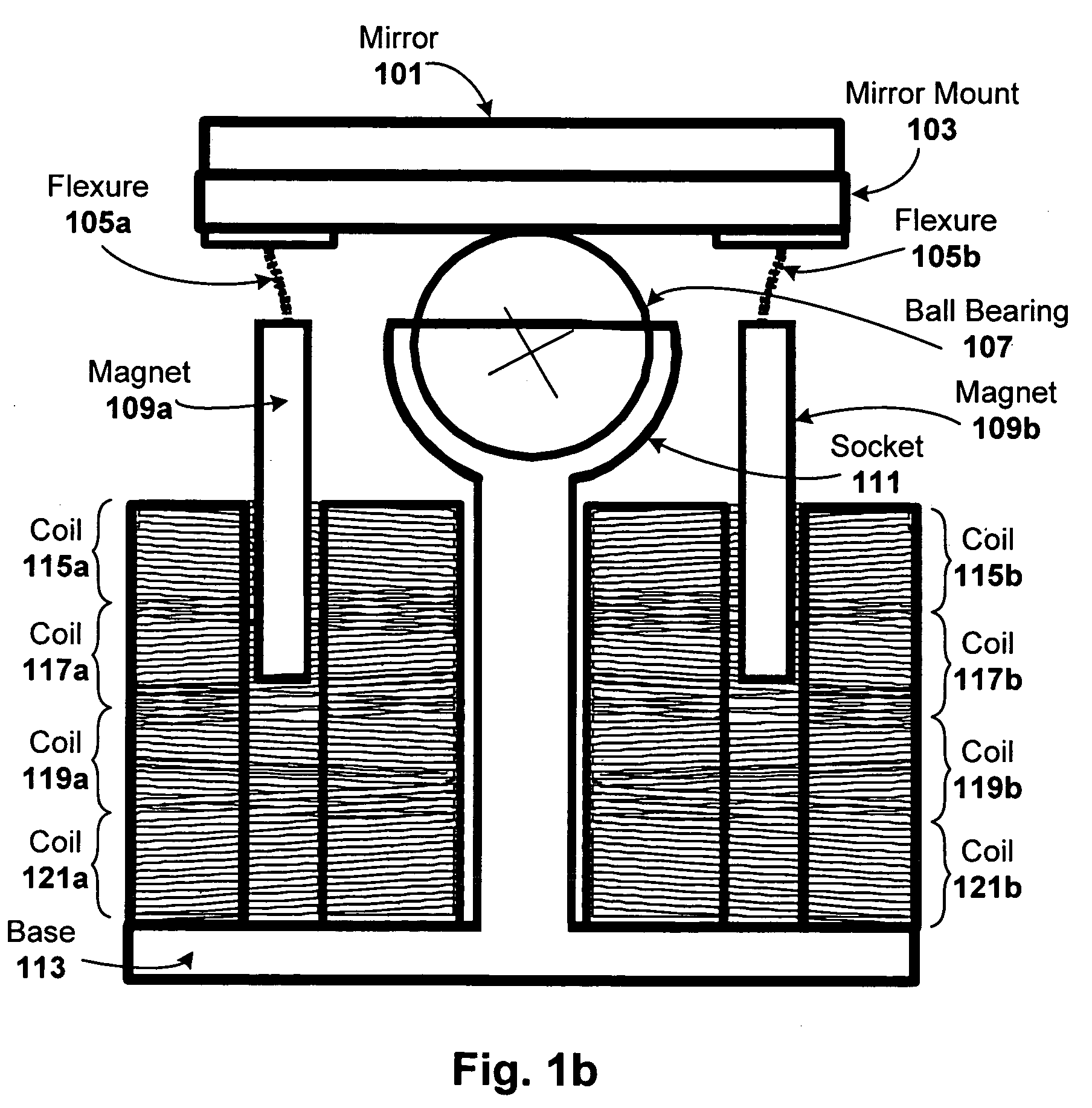
[0018]A pivoting ball joint on which a mirror assembly is attached is employed. The mirror assembly is operatively coupled to an actuator assembly. In one particular embodiment, the actuator assembly includes one or more magnets that slide in and out of wire coils (electro-magnets). When voltage is applied to a coil, the magnet tries to align its respective magnetic field with that of opposite polarity of the coil, thereby causing the ball joint to move, which in turn cause the attached mirror to move to a part...


PUM


Abstract

Compact scanning techniques that can scan a large degree optical solid angle are disclosed. One particular embodiment is a processor controlled scanner that is capable of a large degree optical solid scan angle. Dual axis scan capability can be provided with a single compact package. A pivoting ball joint on which a mirror assembly is attached is employed. The mirror assembly is operatively coupled to an actuator assembly (e.g., electro-magnets or piezoelectric based actuators). When control voltage is applied to the actuator assembly, the ball joint to moves thereby moving the integrally attached mirror assembly.

Description

FIELD OF THE INVENTION[0001]The invention relates to optics, and more particularly, to gimbal techniques for moving an optical mirror.BACKGROUND OF THE INVENTION[0002]There are many conventional ways to scan a laser beam over a solid angle. However, each of these conventional scanning techniques is associated with one or more problems.[0003]For example, dual galvanometers are used in many scanning operations, but have a large dual axis. Dual acousto-optic scanners, dual electro-optic scanners, and dual electro-optic scanners are each associated with a small scan angle (6 optical degrees or less). Dual electro-optic scanners are also physically very large. Dual resonant scanners are associated with a difficult random axis in solid angles unless there is a mechanism to change the resonance of each axis. Dual “stress optical beam” scanners have a small scan angle (15.5 optical degrees using GaAs). Dual gradient liquid crystal scanners also exhibit a small scan angle (0.57 optical degre...

Claims


Application Information

Patent Timeline
IPC IPC(8): G02B26/08
CPCG02B7/1821G02B26/0816
Inventor ODHNER, JEFFERSON E.
Owner BAE SYST INFORMATION & ELECTRONICS SYST INTERGRATION INC
Why Eureka
Try Eureka