Housing type joint

a housing type and joint technology, applied in the field of housing type joints, can solve the problems of heavy weight of the total weight of difficult to compact the housing type joint, and difficulty in assembling the housing type joint at a workplace, etc., to achieve convenient assembling, convenient arrangement, and more lightweight

Active Publication Date: 2008-06-24
VICTAULIC OF JAPAN
View PDF14 Cites 24 Cited by
  • Summary
  • Abstract
  • Description
  • Claims
  • Application Information

AI Technical Summary

Benefits of technology

[0006]This invention is intended to solve the above problems. That is, the object of this invention is to provide a housing type joint easy to be assembled at a workplace as well as easy to be attached to and removed from pipes.
[0008]According to the present invention, since the housing is formed by the at least three arcuate segments and each engagement projection extending outward in a radial direction provided at the elastic ring is inserted (fitted) into each positioning hole provided at each arcuate segment, it is easy to position the housing with respect to the elastic ring. That is, the elastic ring and the housing can be easily arranged at respective suitable positions with respect to a seam of the pipes. In addition, since an attaching operation of the housing type joint is completed by fastening the housing by means of the fastening band and the fastening unit, an assembling operation and an attaching / removing operation of the housing type joint can be easily conducted at a workplace.
[0009]In addition, if the arcuate segment is made from a metal plate, it is possible to make the housing type joint more lightweight and more compact. In addition, the housing type joint can be assembled without using any welding means or any parts such as small screws, so that efficiency of parts management may be improved.

Problems solved by technology

Thus, the total weight of the housing type joint is heavy and it is difficult to make the housing type joint compact.
In addition, it is not easy to assemble the housing type joint at a workplace as well as to attach and remove the housing type joint to and from the two pipes.

Method used


Image

  • Housing type joint
  • Housing type joint
  • Housing type joint

Examples


Embodiment Construction

[0018]Hereinafter, an embodiment of a housing type joint according to the present invention is explained with reference to attached drawings.

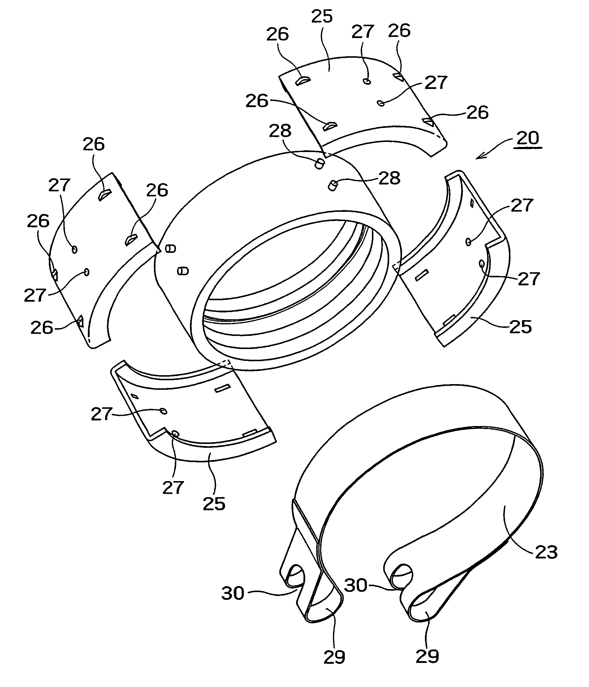
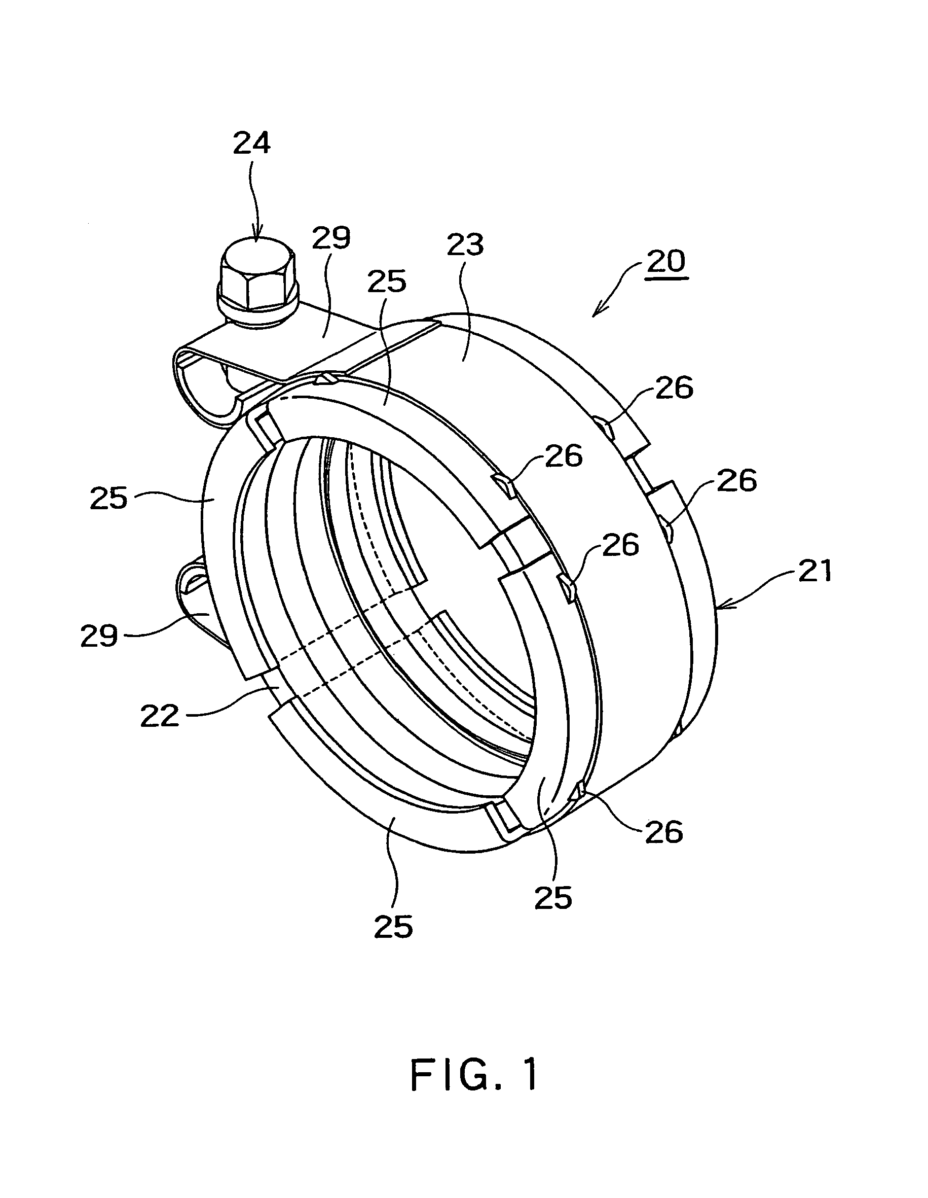
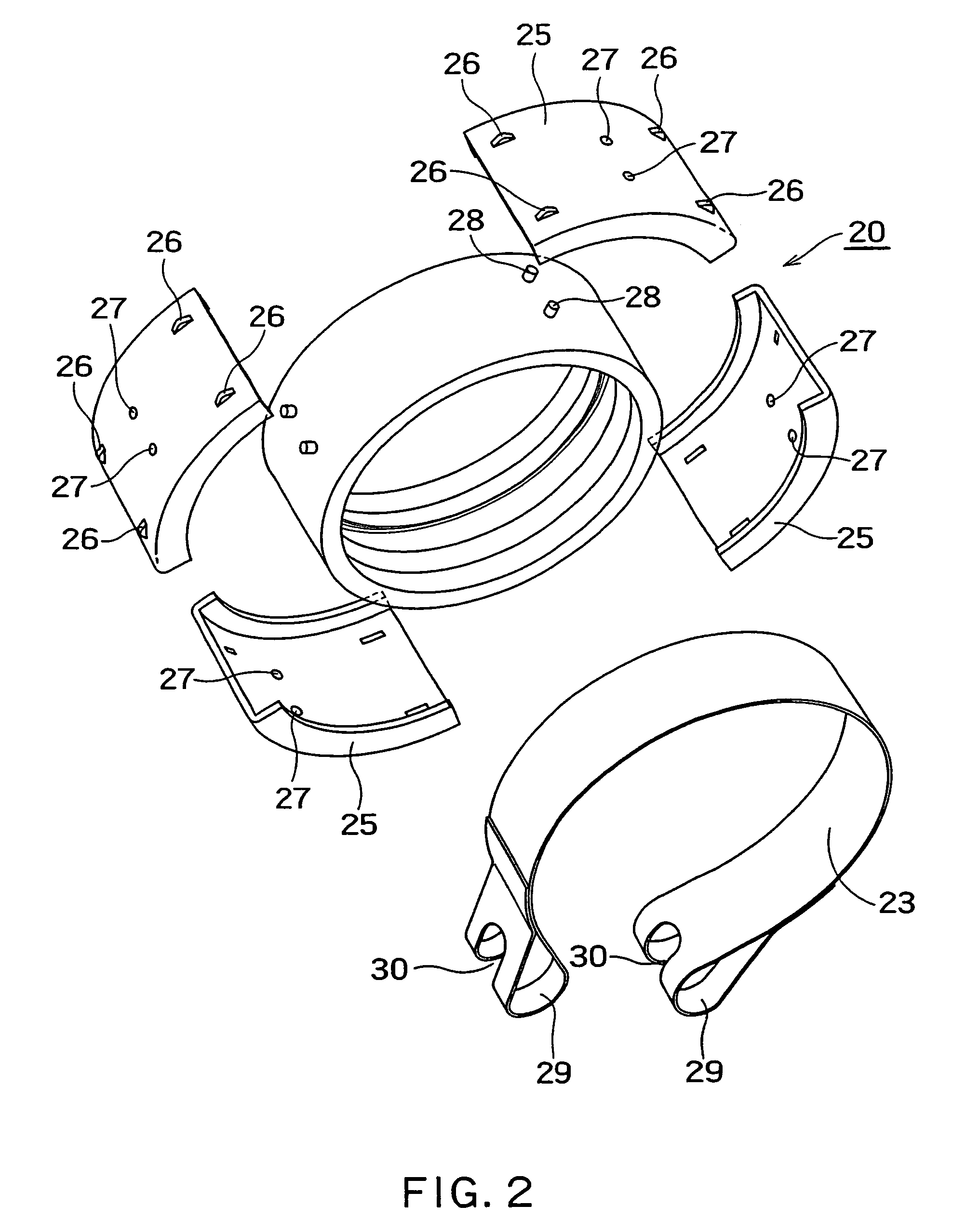
[0019]FIG. 1 is a perspective view showing an embodiment of a housing type joint according to the present invention. FIG. 2 is an exploded perspective view of the housing type joint of FIG. 1.

[0020]As shown in FIGS. 1 and 2, the housing type joint 20 of the present embodiment consists of: a housing 21, an elastic ring 22 arranged inside the housing 21, a fastening band 23 arranged so as to surround an outside surface of the housing 21, and a fastening unit 24 connected to both ends of the fastening band 23.

[0021]The housing 21 is formed by arranging four arcuate segments 25, 25, 25, 25 in a circumferential direction with gaps on or above an outside surface of the elastic ring 22. In the present embodiment, the four arcuate segments 25 have the same shape, and each arcuate segment 25 is a substantially plate-like (planar) member whose section fo...


PUM


Abstract

A housing type joint including: a housing formed by arranging at least three arcuate segments in a circumferential direction with gaps; an elastic ring arranged in the housing for hermetically sealing end portions of a pair of pipes; a fastening band arranged so as to surround an outside surface of the housing and having loop portion at both ends thereof; and a fastening unit that makes the loop portions at both ends of the fastening band closer to each other, in order to make the arcuate segments closer to each other or in contact with each other; wherein the elastic ring has engagement projections at positions located in a circumferential direction thereof with gaps, correspondingly to the respective arcuate segments, each engagement projection extending outward in a radial direction of the elastic ring; each arcuate segment has a positioning hole into which each engagement projection is inserted; and a fastening-band guiding part is provided on an outside surface of each arcuate segment for guiding the fastening band.

Description

FIELD OF THE INVENTION[0001]This invention relates to a housing type joint for hermetically sealing two pipes whose edge portion has a circular groove, in particular, to a housing type joint that is lightweight and compact and easy to be attached and removed.BACKGROUND ART[0002]As a housing type joint that hermetically seals connecting portions of small-diameter pipes such as water-supply pipes, a housing type joint having a structure shown in FIG. 8 is used in various industrial fields.[0003]The housing type joint as shown in FIG. 8 consists of: a pair of semicircular joint segments 1, 2 made by casting; bolt seats 3, 3 integrally formed at both end portions of one semicircular joint segment 1; bolt seats 4, 4 integrally formed at both end portions of the other semicircular joint segment 2; a space 7 formed in the semicircular joint segments 1, 2 for containing end portions of two pipes 5, 6; an elastic ring 8 arranged in the space 7 formed in the semicircular joint segments 1, 2 f...

Claims


Application Information

Patent Timeline
Patent Type & Authority Patents(United States)
IPC IPC(8): F16L17/03F16L17/04
CPCF16L17/04F16L21/065
Inventor NODA, YUJI
Owner VICTAULIC OF JAPAN
Why Eureka
Try Eureka