Secure fiber optic network keyed connector assembly

a fiber optic network and keyed connector technology, applied in the direction of optical elements, coupling device connections, instruments, etc., can solve the problems of connector not fitting, physical tampering or access to secure data channels, and encryption and decryption algorithms cannot preven

Inactive Publication Date: 2008-06-24
ORTRONICS INC +1
View PDF46 Cites 138 Cited by
  • Summary
  • Abstract
  • Description
  • Claims
  • Application Information

AI Technical Summary

Benefits of technology

[0012]An inner door associated with the present disclosure includes a main locking boss adapted to substantially engage a main locking slot defined on the outer door. Engaging of the main locking boss and the main locking slot prevents the rotation of the security feature during illegitimate connector insertion. During legitimate connector insertion pressure is applied to the mating keying boss of the inner door by the protruding keying boss of the first connector passing through the aperture of the outer door causing the main locking boss to disengage from the main locking slot allowing the security feature to rotate and the connectors to communicate. The outer door also defines a relief slot adapted to allow for the main locking boss to fit neatly in a back opening of the outer door during rotation of the security feature. Moreover, the outer door typically further defines a pass through aperture adapted to prevent damaging a ferrule included on the first connector during legitimate or illegitimate connector insertion.
[0014]In an exemplary embodiment, the present disclosure describes a secure connector system having an assembly including: (i) a front opening cavity; (ii) a rear opening cavity; and (iii) a security feature. The front opening cavity and the rear opening cavity are each adapted to accept a keyed mating connector having a protruding mating keying boss. The security feature is positioned on a bottom surface of the front opening cavity and prevents communication between two illegitimate keyed mating connectors and allows communication between two legitimate mating connectors by the mechanism of an inner door standing vertical when engaged and rotating downward when disengaged.
[0015]An exemplary security feature includes: (i) an inner door defining a mating keying sloped aperture adapted to accept the mating keying boss of the first mating connector; (ii) two die cast boss elements attached to the sides of the inner door and adapted to slide into two channels further defined on the bottom surface of the opening cavity; (iii) a cam shaped element attached to a rear side of the inner door; (iv) a leaf spring interacting with the cam shaped element wherein the leaf spring applies pressure to the cam shaped element holding the inner door upright in the absence of external pressure; and (v) a locking boss extending outwardly on a front face of the inner door in contact with a lip feature included on the opening cavity of the assembly and adapted to prevent rotation of the inner door during illegitimate connector insertion.

Problems solved by technology

Although these security techniques have generally been successful in preventing a non-physical security breach, they do not prevent physical tampering or access to secure data channels.
For example, encryption and decryption algorithms do not prevent a person internal to an organization from gaining physical access to secure data channels from which said person is restricted.
If the user attempts to insert the given connector on the patch cable into any adapter other than one designed for it, the connector will not fit and a network connection will not be made.
Although these embodiments provide for preventative security breach through improper mating geometry, they do not provide an optical barrier to the receiving means.

Method used


Image

  • Secure fiber optic network keyed connector assembly
  • Secure fiber optic network keyed connector assembly
  • Secure fiber optic network keyed connector assembly

Examples


Embodiment Construction

)

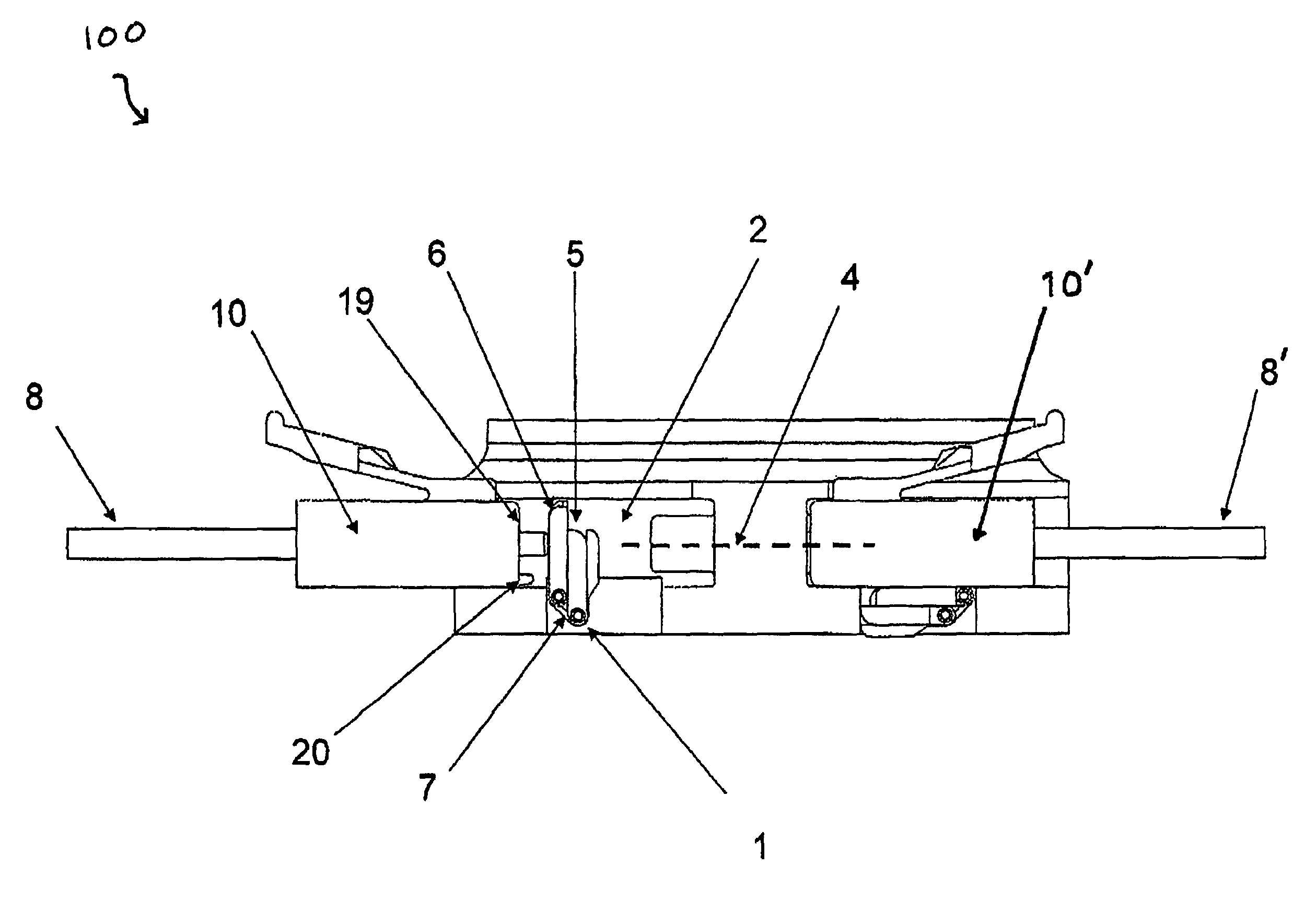
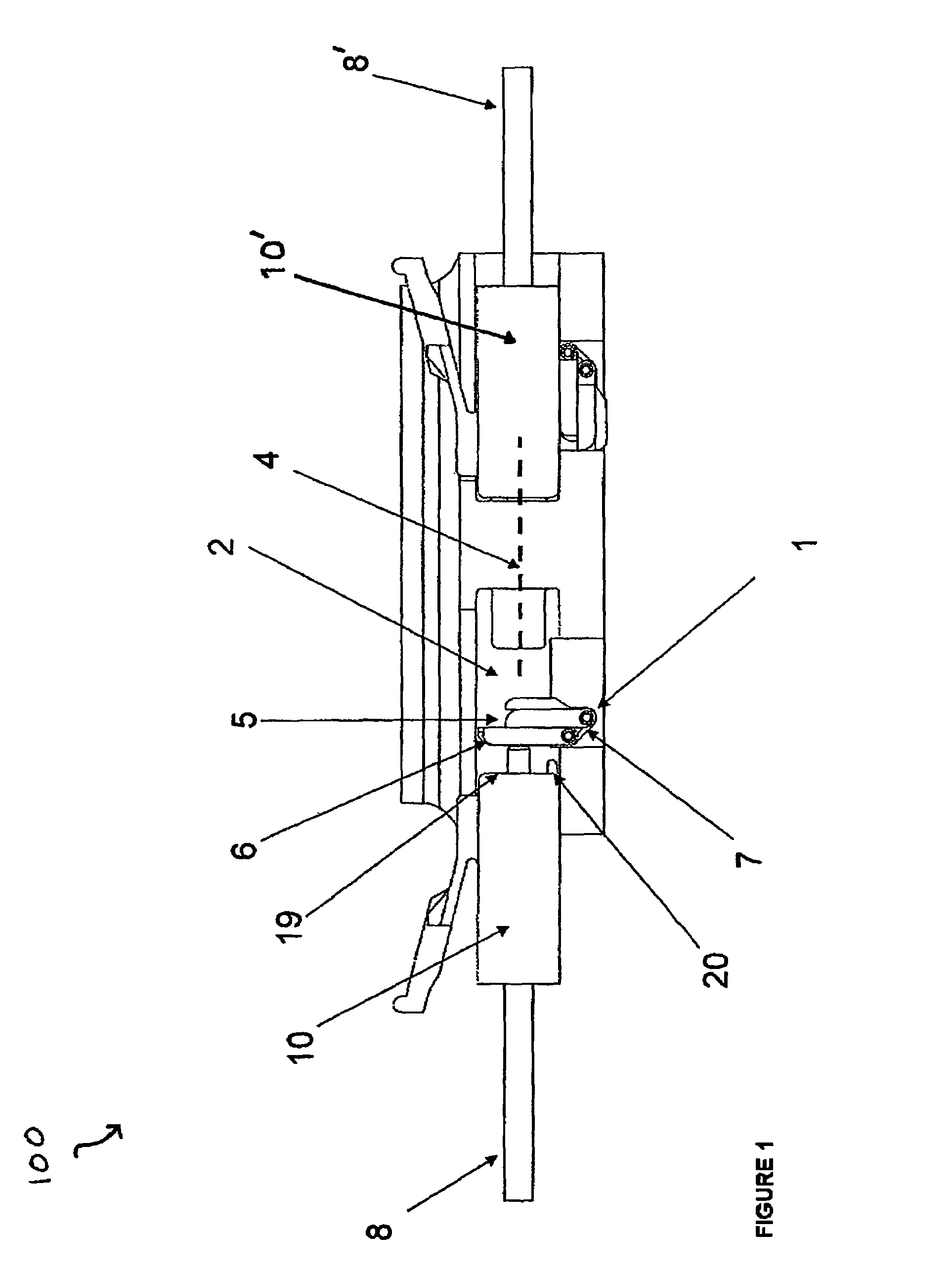
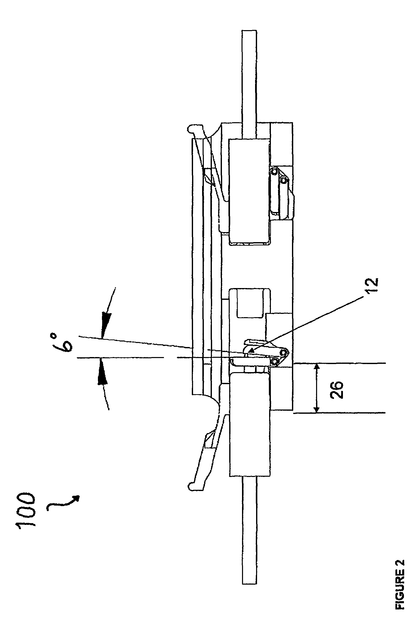
[0036]The present disclosure provides for a uniquely advantageous system that is effective in securing a multiport fiber optic connector assembly. FIG. 1 illustrates an exemplary embodiment of a single port assembly 100. A network system typically will have a plurality of assemblies 100 each defining a unique keyed solution consistent with the present disclosure. As described above, a patch cord hosting a connector at the connection end will be a specified color, e.g., blue, green, red, etc. Each color represents a different security / access level for a user.

[0037]An exemplary assembly 100 associated with the present disclosure includes a security feature 1, typically a spring loaded dual shutter door apparatus, integrated with an internal front opening cavity 2. Typically, security feature 1 includes a torsion spring 7, an outer door 6 and an inner door 5. Security feature 1 is adapted to serve as a barrier to optical pathway 4 from optical communication between two mating fiber op...


PUM


Abstract

Systems and methods for securing a keyed fiber optic network assembly are provided. A typical network system includes an assembly having a security feature and adapted to facilitate fiber optic communication between two mating fiber optic connectors. The security feature is uniquely keyed to disengaged when mated with a corresponding uniquely keyed connector. The security feature includes at least an inner door and a spring and is adapted to prevent optical communication and mating with a receiving connector during illegitimate connector insertion. A typical network includes a plurality of assemblies each having a uniquely keyed security feature. Each of the plurality of assemblies is color coded to match with a legitimate color coded connector to provide guidance to a network user. The connector and the security feature are uniquely keyed through unique positioning of protruding bosses.

Description

BACKGROUND[0001]1. Technical Field[0002]The present disclosure relates to systems and methods for securing a fiber optic network assembly through a keyed connector solution.[0003]2. Background Art[0004]Many transactions take place everyday over the Internet, increasing a need for secure Ethernet communications. Typically, network security is handled in an Ethernet's layers 2-7, providing packet encryption and decryption algorithms up to 256 bit, which is generally considered virtually unbreakable by mathematicians and programmers alike. Although these security techniques have generally been successful in preventing a non-physical security breach, they do not prevent physical tampering or access to secure data channels. For example, encryption and decryption algorithms do not prevent a person internal to an organization from gaining physical access to secure data channels from which said person is restricted. A person having a low level security clearance can sit at another person's ...

Claims


Application Information

Patent Timeline
Patent Type & Authority Patents(United States)
IPC IPC(8): H01R13/44
CPCG02B6/3831G02B6/3897
Inventor MURANO, ADAMRYNASKI, CHESTER
Owner ORTRONICS INC
Why Eureka
Try Eureka