Self-aligning connector

a self-aligning, connector technology, applied in the direction of coupling contact members, coupling device connections, incorrect coupling prevention, etc., can solve the problems of difficult or impossible mounting or providing such a connecting structure, and achieve the effect of large deviation and downsizability

Inactive Publication Date: 2008-06-24
THE FUJIKURA CABLE WORKS LTD
View PDF19 Cites 8 Cited by
  • Summary
  • Abstract
  • Description
  • Claims
  • Application Information

AI Technical Summary

Benefits of technology

[0007]The present invention has been made in light of the above-described circumstances. An object of the present invention is to provide a self-aligning connector (structure), wherein a relatively large deviation during assembly can be absorbed, wherein a centering function thereof is inherently superior to that obtainable using most conventional ones, and wherein it is downsizable.

Problems solved by technology

As a result, it is difficult or impossible to mount or provide such a connecting structure where there is not sufficient space.

Method used


Image

  • Self-aligning connector
  • Self-aligning connector
  • Self-aligning connector

Examples


Embodiment Construction

[0023]Hereinafter, embodiments of the present invention will be described in detail with reference to the drawings.

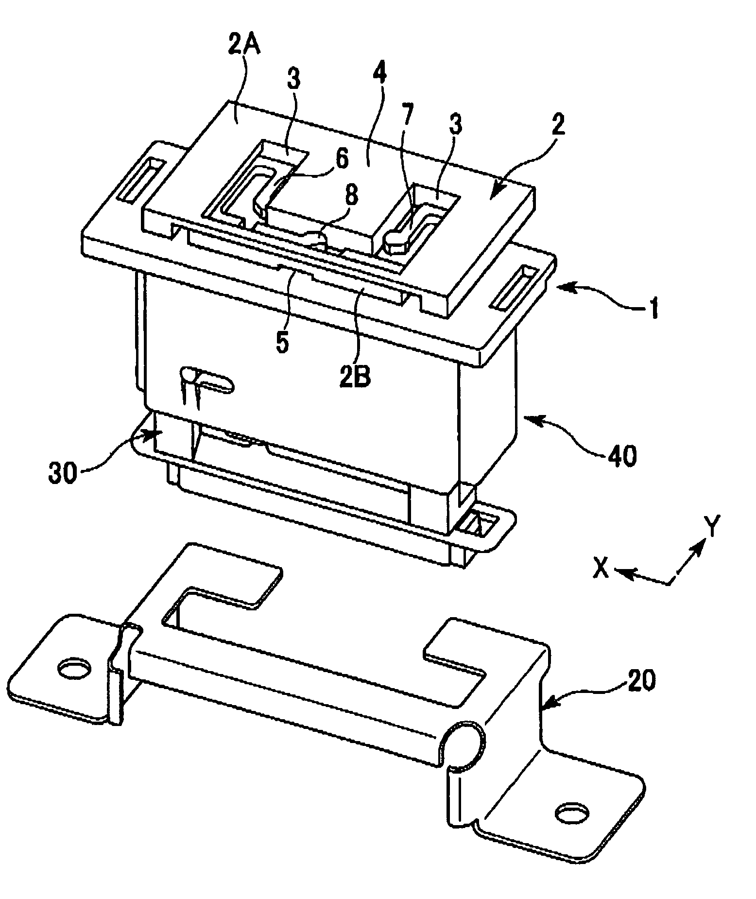
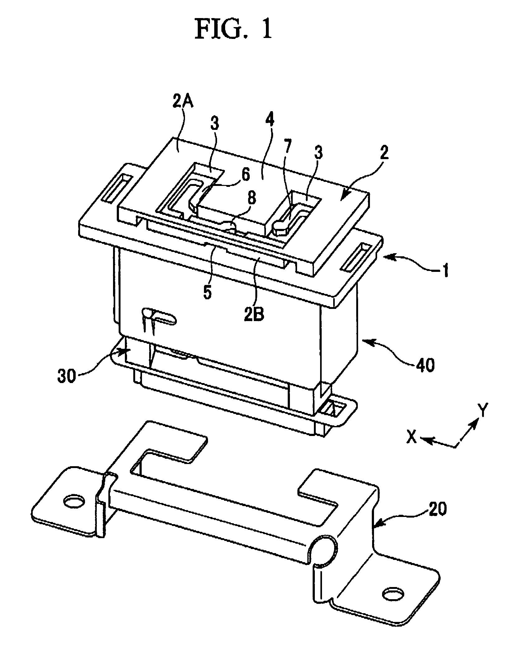
[0024]FIG. 1 illustrates an embodiment of a self-aligning connector assembly or parts of a modular struggle of a vehicle, such as an automotive vehicle, but not limited thereto, according to the present invention. A bracket 20 (one securing portion) is fixed to, for example, a vehicle body 10 of the automotive vehicle. A female connector 30 is secured to the securing bracket 20. A male connector 40 fits in the female connector 30. A connector cover 1 covers the male connector 40. A slide plate 2 is secured to the connector cover 1.

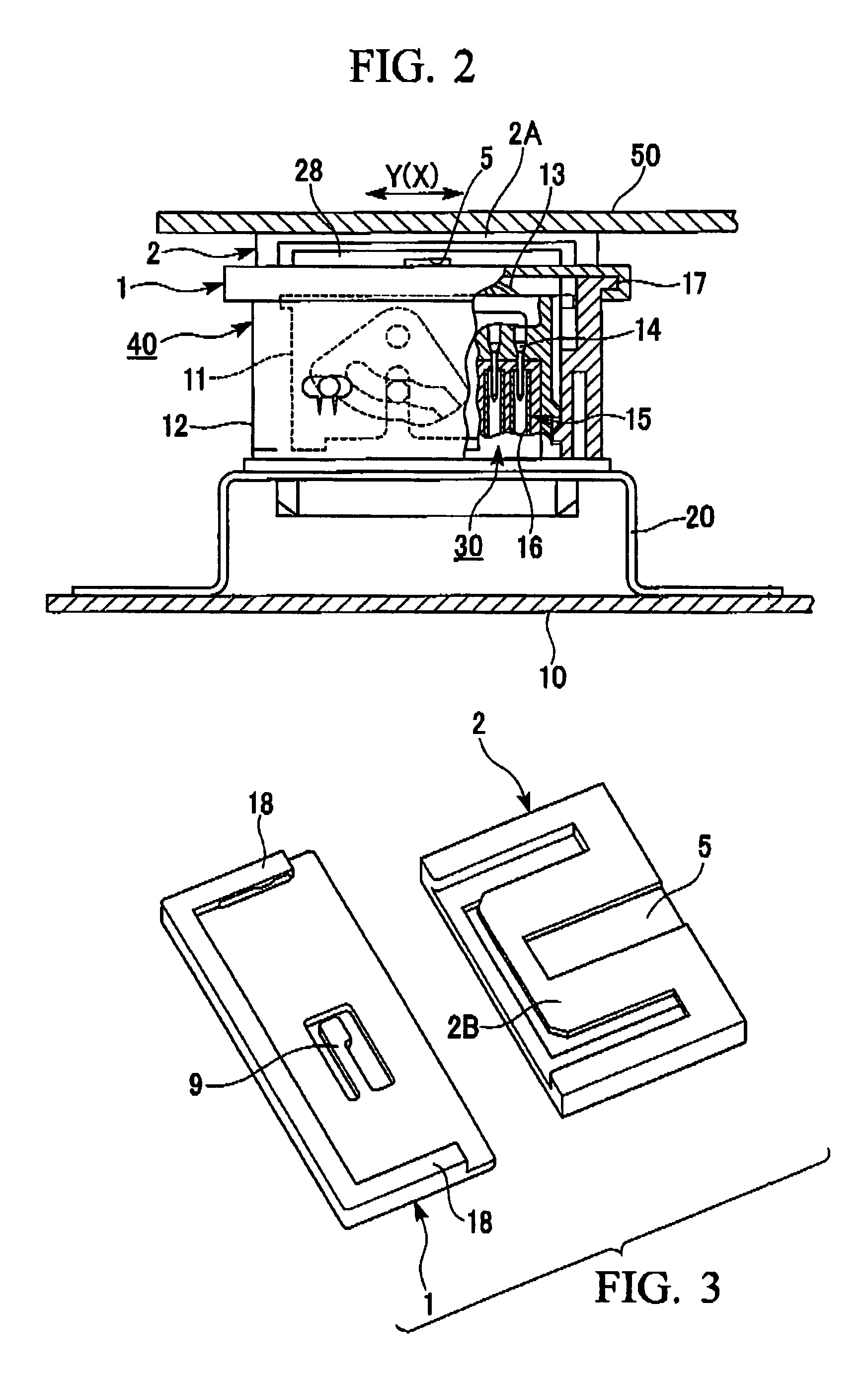
[0025]The slide plate 2 is fixed to, for example, a center console panel 50 (another securing portion) of the automotive vehicle (see FIG. 2). The slide plate 2 has an upper plate 2A in which a U-shaped opening 3 is formed such that a centrally-located extended piece 4 is provided. A lower plate 2B is secured to the upper plate 2A, maintaining...


PUM


Abstract

A self-aligning connector, comprising: a female connector which is adapted to include at least one electrical component and to be optionally secured to one securing portion; a male connector connectable to the female connector, the male connector being adapted to include at least one electrical component and to be optionally secured to another securing portion; and at least one connector cover and at least one slide plate, which are disposed between the one securing portion and the another securing portion; wherein the at least one connector cover includes a plurality of resilient pawls, which has distal ends located in the vicinity of a connector cover center portion in front-rear and left-right directions in the plane of the at least one connector cover; wherein the at least one slide plate includes a receiving portion in which resilient pawls are inserted and engaged; and wherein the resilient pawls absorb deviations in the front-rear and left-right directions occurring at the time of connecting the female and the male connectors to properly align the female and the male connectors.

Description

BACKGROUND OF THE INVENTION[0001]1. Field of the Invention[0002]The present invention relates to a self-aligning connector which cal be used when parts of a modular structure of a vehicle or the like are assembled and which has a function of self-aligning,[0003]Priority is claimed on Japanese Patent Application No. 2005-63006, filed Mar. 7, 2005, the content of which is incorporated herein by reference.[0004]2. Description of the Related Art[0005]An example of a conventional connector with a self-aligning function is shown in FIG. 7, which is used when a female connector 100 and a male connector 101 are fitted to each other. A vehicle, e.g., an automotive vehicle, is provided with an instrument panel which has a partition wall with an opening into which the female connector 100 is fitted. The female connector has four spring pieces 102 formed therein. A guide projecting portion 103 which is latched by these spring pieces 102 of the female connector 100 is inserted in a guide groove ...

Claims


Application Information

Patent Timeline
Patent Type & Authority Patents(United States)
IPC IPC(8): H01R13/64
CPCH01R13/6315H01R2201/26H01R13/73H01R13/514H01R13/22
Inventor NOGUCHI, TAKAMITSUISHIKAWA, SHIGERUHAYASHI, KOTARO
Owner THE FUJIKURA CABLE WORKS LTD
Why Eureka
Try Eureka