Compensating for repeatable phase error when servo writing a disk drive from spiral tracks

a spiral track and disk drive technology, applied in the field of disk drives, can solve the problems of '679 patent does not compensate for repeatable phase errors', the internal servo writer is expensive and requires a clean room environment, and the external servo writer is an expensive bottleneck in the disk drive manufacturing process

Inactive Publication Date: 2008-06-24
WESTERN DIGITAL TECH INC
View PDF39 Cites 137 Cited by
  • Summary
  • Abstract
  • Description
  • Claims
  • Application Information

AI Technical Summary

Benefits of technology

[0007]An embodiment of the present invention comprises a method of writing product servo sectors on a disk of a disk drive. The disk drive comprises control circuitry and a head disk assembly (HDA) comprising the disk, an actuator arm, a head coupled to a distal end of the actuator arm, and a voice coil motor for rotating the actuator arm about a pivot to position the head radially over the disk. The disk comprises a plurality of spiral tracks, each spiral track comprises a high frequency signal interrupted periodically by a sync mark. The head internal to the disk drive is used to read the spiral tracks to generate a read signal, and the sync marks are detected from the read signal to generate

Problems solved by technology

However, external servo writers are expensive and require a clean room environment so that a head positioning pin can be inserted into the head disk assembly (HDA) without contaminating the disk.
Thus, external servo writers have become an expensive bottleneck in the disk drive manufacturing process.
However, the '679 patent does not compensate fo

Method used


Image

  • Compensating for repeatable phase error when servo writing a disk drive from spiral tracks
  • Compensating for repeatable phase error when servo writing a disk drive from spiral tracks
  • Compensating for repeatable phase error when servo writing a disk drive from spiral tracks

Examples


Embodiment Construction

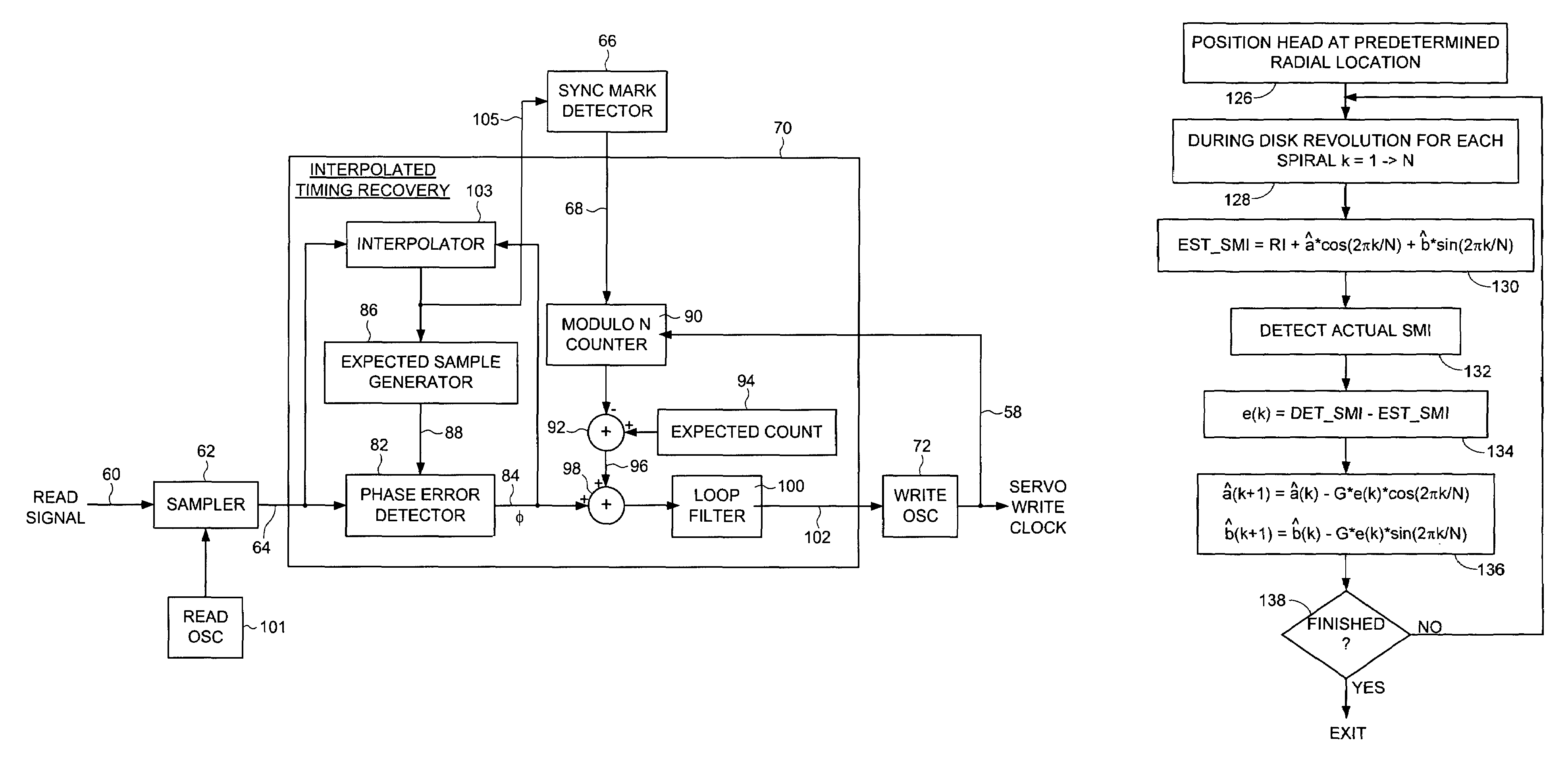
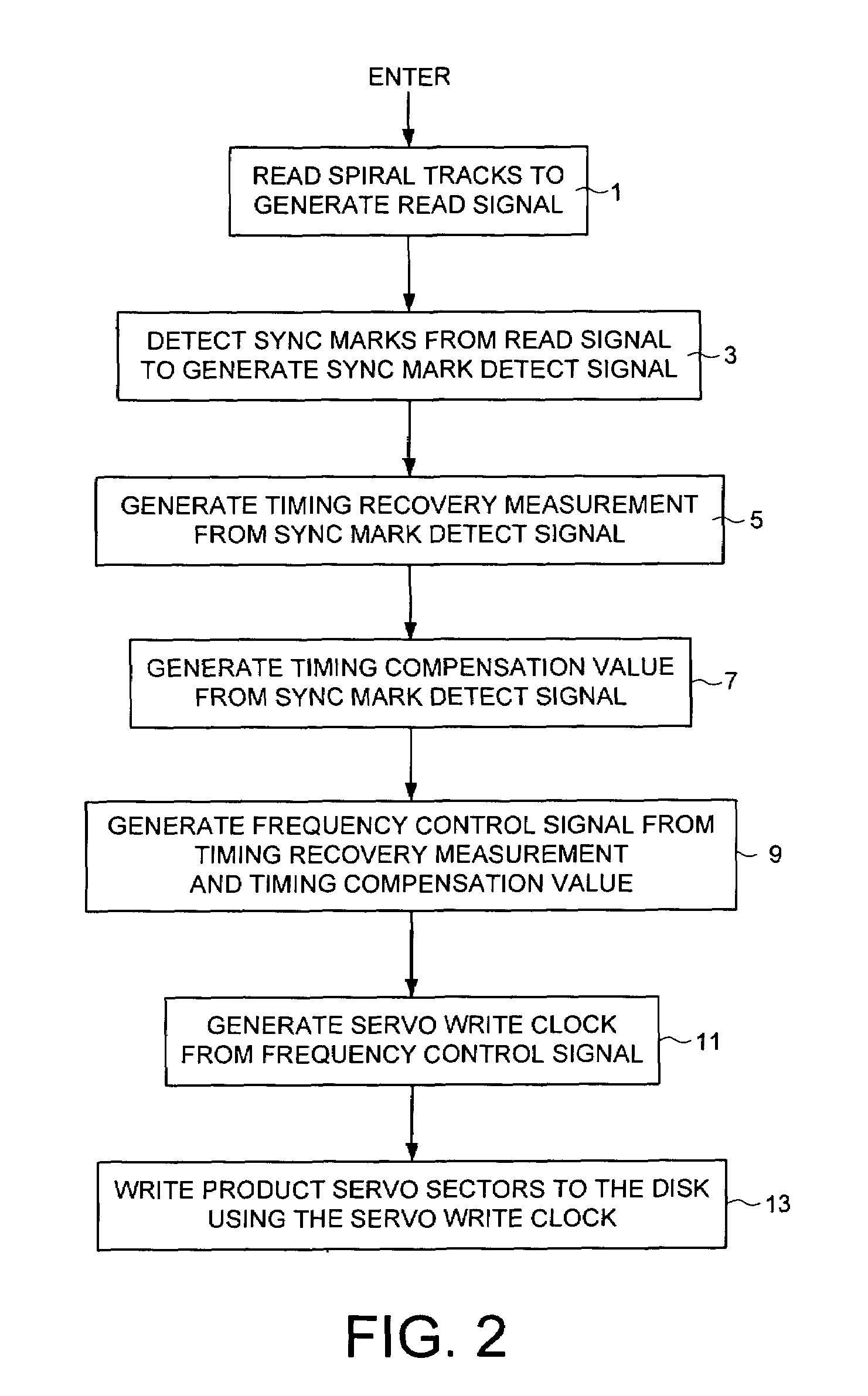
[0036]FIG. 2 shows a flow diagram for writing product servo sectors on a disk of a disk drive according to an embodiment of the present invention. The disk drive comprises control circuitry and a head disk assembly (HDA) comprising the disk, an actuator arm, a head coupled to a distal end of the actuator arm, and a voice coil motor for rotating the actuator arm about a pivot to position the head radially over the disk. The disk comprises a plurality of spiral tracks, each spiral track comprises a high frequency signal interrupted periodically by a sync mark. At step 1 the head internal to the disk drive is used to read the spiral tracks to generate a read signal, and at step 3 the sync marks are detected from the read signal to generate a sync mark detect signal. At step 5 a timing recovery measurement is generated in response to the sync mark detect signal, wherein the timing recovery measurement comprises a sinusoidal component. At step 7 a timing compensation value is generated i...


PUM


Abstract

A method of servo writing a disk of a disk drive is disclosed. The disk comprises a plurality of spiral tracks, wherein each spiral track comprises a high frequency signal interrupted periodically by a sync mark. A timing recovery measurement is generated in response to the sync marks, wherein the timing recovery measurement comprises a sinusoidal component. A timing compensation value is generated in response to the sync marks which estimates the sinusoidal component in the timing recovery measurement. A frequency control signal is generated in response to the timing recovery measurement and the timing compensation value, a servo write clock is generated in response to the frequency control signal, and the servo write clock and the head internal to the disk drive are used to write the product servo sectors to the disk.

Description

BACKGROUND OF THE INVENTION[0001]1. Field of the Invention[0002]The present invention relates to disk drives. More particularly, the present invention relates to compensating for repeatable phase error when servo writing a disk drive from spiral tracks.[0003]2. Description of the Prior Art[0004]When manufacturing a disk drive, product servo sectors 20-2N are written to a disk 4 which define a plurality of radially-spaced, concentric servo tracks 6 as shown in the prior art disk format of FIG. 1. Each product servo sector (e.g., servo sector 24) comprises a preamble 8 for synchronizing gain control and timing recovery, a sync mark 10 for synchronizing to a data field 12 comprising coarse head positioning information such as a track number, and servo bursts 14 which provide fine head positioning information. During normal operation, the servo bursts 14 are processed by the disk drive in order to maintain a head over a centerline of a target track while writing or reading data. In the ...

Claims


Application Information

Patent Timeline
IPC IPC(8): G11B5/09G11B21/02
CPCG11B5/59627G11B5/59661G11B20/10037G11B20/10222G11B20/1403G11B5/59644G11B2020/1282G11B2020/1287
Inventor SHEH, EDGAR D.CAI, YILIN
Owner WESTERN DIGITAL TECH INC
Why Eureka
Try Eureka