Method for handoff between an asynchronous CDMA base station and a synchronous CDMA base station

a technology cdma base station, which is applied in the field of wireless communication systems, can solve the problems of inability to determine which pilot signal is being transmitted by which base station, the remote unit is unlikely to have system time information of synchronous base station to a sufficient accuracy, and the difficulty in receiving universal time synchronization signals using gps, etc., to achieve the effect of reducing the number of ambiguities

Inactive Publication Date: 2008-06-24
QUALCOMM INC
View PDF8 Cites 15 Cited by
  • Summary
  • Abstract
  • Description
  • Claims
  • Application Information

AI Technical Summary

Benefits of technology

[0022]The present invention provides a method for determining a pilot channel PN offset of a pilot channel transmitted by a wireless base station. It is anticipated that this method would be employed by a wireless receiver such as a mobile station. In a first embodiment, the method includes correlating a PN sequence with a received pilot signal to acquire a PN frame timing, receiving at least one search code burst aligned with the PN frame timing, the at least one search code burst signifying the pilot channel PN offset, and comparing the at least one search code burst to a set of codewords, each codeword representing a predetermined PN offset. From the search code bursts, the mobile station is able to quickly determine the PN offset of the transmitting base station, and thereby identify it.

Problems solved by technology

For example, in a system which is deployed underground, such as in a subway system, it can be difficult to receive a universal time synchronization signal using GPS.
Thus, when a remote unit is in communication with an asynchronous base station, and has not been recently in communication with a synchronous base station, the remote unit is unlikely to have system time information of the synchronous base stations to a sufficient accuracy.
Unless the remote unit already knows system time of the synchronous base stations to a sufficient accuracy, the remote unit will be unable to determine which pilot signal is being transmitted by which base station.
In other words, although the remote unit is able to distinguish that there are two different synchronous base stations due to their different relative PN sequence offsets, the remote unit is unable to determine the identity of either synchronous base station based on their pilot signals alone because the remote station does not have an absolute time reference with which to compare the two PN sequence offsets.
This delay can undesirably affect the timing of a handoff from the asynchronous base station to the synchronous base station, particularly in a fading environment.
In some instances, the delay associated with the remote unit having to determine the system identification of the target synchronous base station(s) by demodulating a conventional sync channel message would be unacceptably long, causing degradation or even dropping of a call in progress.

Method used


Image

  • Method for handoff between an asynchronous CDMA base station and a synchronous CDMA base station
  • Method for handoff between an asynchronous CDMA base station and a synchronous CDMA base station
  • Method for handoff between an asynchronous CDMA base station and a synchronous CDMA base station

Examples


first embodiment

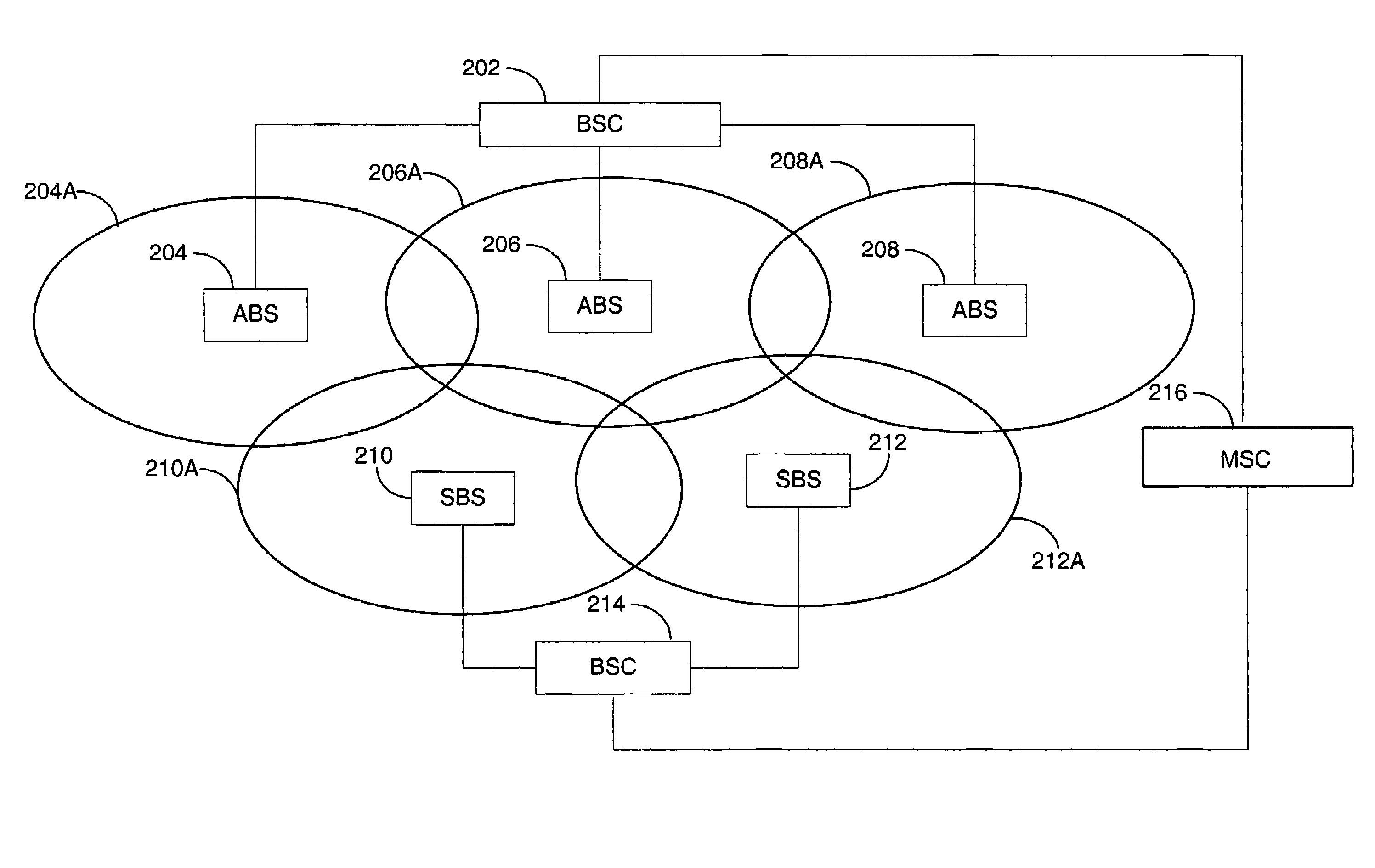
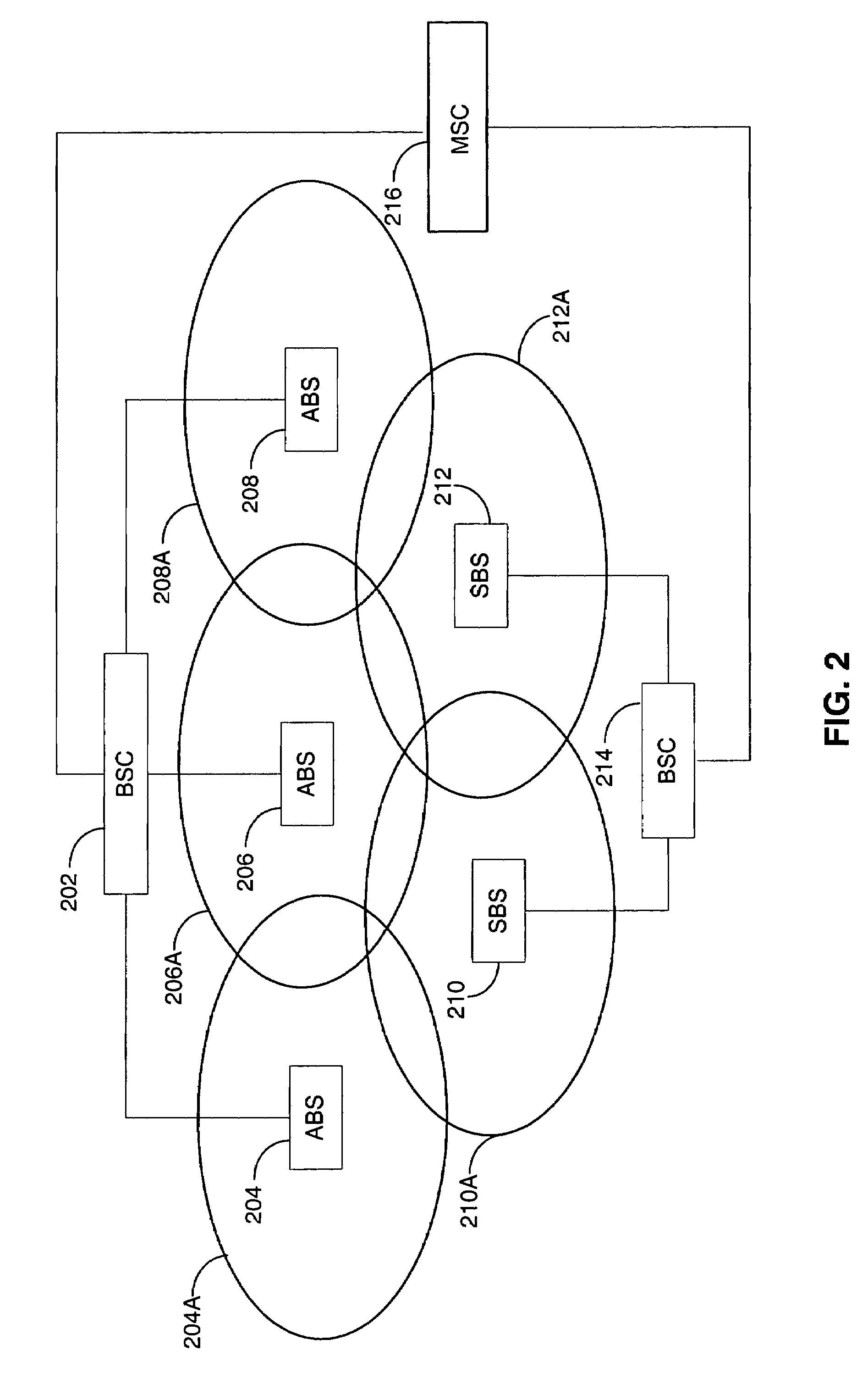
[0042]Various embodiments of the present invention will now be described. The present invention seeks to determine the pilot offset and frame phase within system time. As used herein, the term “phase” refers to frame-level phase. Turning now to FIG. 3, a timing diagram of the present invention is illustrated. In FIG. 3, an 80 ms sync channel superframe 300, three 26.67 ms pilot channel frames 302, 304, 306, and a sequence 308-312 of search code bursts are illustrated. These channels are transmitted by one or more of the synchronous base stations 210, 212. The sync channel superframe 300 may be a conventional cdma2000 sync channel superframe. The pilot channel frames 302, 304, 306 may be three consecutive frames of a conventional cdma2000 pilot channel. As used herein, the phrase “pilot channel frame” refers to a single PN sequence period. However, it should be noted at the outset that the numerology used in the Figures is merely exemplary and is used for teaching the present inventi...

second embodiment

[0047]Turning now to FIG. 5, a timing diagram of the present invention is illustrated. In FIG. 5, similar to that of FIG. 3, an 80 ms sync channel superframe 300, three 26.67 ms pilot channel frames 302, 304, 306, and a sequence 508-512 of search code bursts are illustrated. However, the search code channel of FIG. 5 differs from that of FIG. 3 in a number of ways. In FIG. 5, each search code burst 508, 510, 512 is comprised of 16 groups of 16 chips. Each 16-chip group is either a particular fixed chip pattern (e.g., [0100110100111010]) or its complement (e.g., [1011001011000101]). It should be noted that these patterns may be arbitrarily constructed, although it may be preferable to have an equal number of ones and zeros to avoid introducing any transmit power bias. Thus, a total of 216 separate search code patterns are possible. Of these, 1536 are used to represent the PN offset (512 possible) and 80 ms phase (3 possible). A single burst is repeated 32 times throughout, and aligne...

third embodiment

[0048]A timing diagram of the present invention is illustrated in FIG. 6. In FIG. 6, a sequence of primary search code bursts 608 and a sequence of secondary search code bursts 610A-614B are illustrated, along with three consecutive pilot channel PN frames 302-306. The sequence of primary search code bursts 608 are common to all base stations transmitting the primary search code bursts 608. Each primary search code burst 608 is identical and repeated every X microseconds, where X in the exemplary embodiment of FIG. 6 is 625 microseconds. The primary search code bursts 608 are aligned with the beginning of an 80 ms system time frame 600. In other words, the first primary search code burst 608 occurs at the beginning of each 80 ms system time frame 600, and is repeated throughout the frame 600.

[0049]A repeating sequence of secondary search codes 610A-614B is transmitted separately from the primary search codes 608. The secondary search codes 610A-614B are a repeating sequence of two-b...


PUM


Abstract

An improved method for facilitating handoff between an asynchronous and a synchronous base station. A method for determining a pilot channel PN offset of a pilot channel transmitted by a wireless base station. In a first embodiment, the method includes correlating a PN sequence with a received pilot signal to acquire a PN frame timing, receiving at least one search code burst aligned with the PN frame timing, the at least one search code burst signifying the pilot channel PN offset, and comparing the at least one search code burst to a set of codewords, each codeword representing a predetermined PN offset. From the search code bursts, the mobile station is able to quickly determine the PN offset of the transmitting base station, and thereby identify it. Methods for transmitting a complementary set of forward link channels are also disclosed.

Description

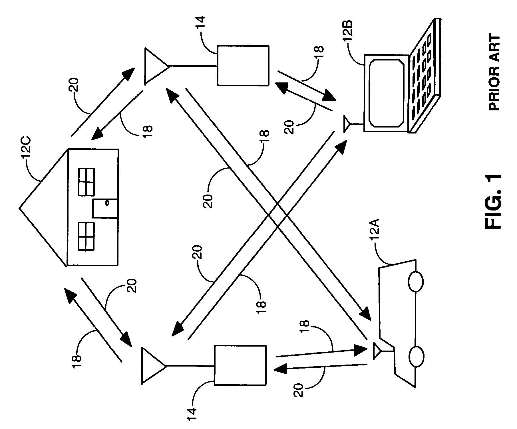
CLAIM OF PRIORITY UNDER 35 U.S.C. §120[0001]The present Application for Patent is a Continuation and claims priority to patent application Ser. No. 09 / 515,041 entitled “Method and Handoff Between an Asynchronous CDMA Base Station and a Synchronous CDMA Base Station,” filed Feb. 25, 2000, now U.S. Pat. No. 6,724,739, and assigned to the assignee hereof and hereby expressly incorporated by reference herein.[0002]This application claims the benefit of U.S. Provisional Application No. 60 / 121,611, entitled “Asynchronous Operation”, filed Feb. 25, 1999.BACKGROUND OF THE INVENTION[0003]I. Field of the Invention[0004]The present invention relates to wireless communication systems. More particularly, the present invention relates to a novel and improved method for enabling a mobile station to execute a handoff between an asynchronous base station and a synchronous base station in a CDMA wireless communication system.[0005]II. Description of the Related Art[0006]FIG. 1 is an exemplifying embo...

Claims


Application Information

Patent Timeline
Patent Type & Authority Patents(United States)
IPC IPC(8): H04Q7/00H04B7/216H04Q7/20H04B1/707H04W36/14
CPCH04B1/7075H04W36/0083H04B2201/70701H04W36/14
Inventor TIEDEMANN, JR., EDWARD G.TERASAWA, DAISUKESARKAR, SANDIP
Owner QUALCOMM INC
Why Eureka
Try Eureka