Method and apparatus for image interpolation based on adaptive polyphase filters

a polyphase filter and adaptive technology, applied in the field of image interpolation, can solve the problems of generating ringing artifacts, blurring, and sharp edges tend to be smoothed and blurred, and achieve the effect of better image interpolation results

Inactive Publication Date: 2008-06-24
SAMSUNG ELECTRONICS CO LTD
View PDF23 Cites 28 Cited by
  • Summary
  • Abstract
  • Description
  • Claims
  • Application Information

AI Technical Summary

Benefits of technology

[0010]The present invention addresses the above problems. Accordingly, in one embodiment the present invention provides a method and system for reproducing an original image as an interpolated output image in which the original image is represented by digital input pixel data. Two polyphase filters are used to interpolate a selected image position, and the output of the two filters are selectively combined to achieve a better image interpolation result. A controller is designed based on local image high-frequency levels and used to adaptively select or combine the filter output values, so that the image interpolation artifacts mentioned above can be avoided.
[0014]As such, if image high frequency level at the given interpolation position is estimated high, the output from the sharp filter is given more weight in determining the interpolation value for the given location. Otherwise, the output from the smooth filter is given more weight. Through such an example adaptive combination of the filter output values from a sharp filter and a smooth filter in the interpolation process, the sharpness of image edges can be well preserved without introducing either blurring edge artifacts or ringing artifacts.

Problems solved by technology

However, it generates some ringing artifacts in smooth image areas that have a sharp edge in the vicinity.
The output from the smooth filter has no ringing artifact, but originally sharp edges tend to be smoothed and blurred.

Method used


Image

  • Method and apparatus for image interpolation based on adaptive polyphase filters
  • Method and apparatus for image interpolation based on adaptive polyphase filters
  • Method and apparatus for image interpolation based on adaptive polyphase filters

Examples


Embodiment Construction

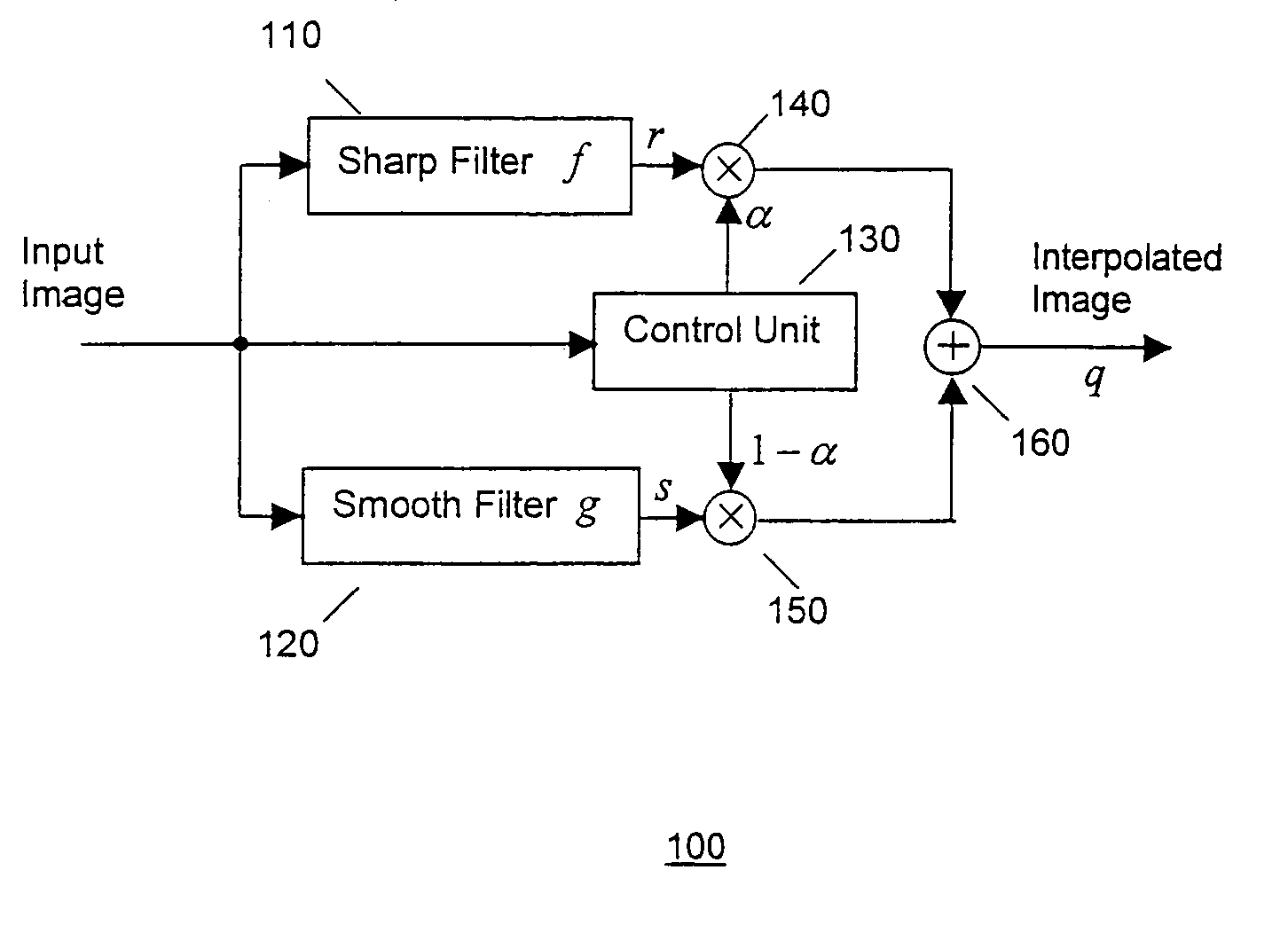
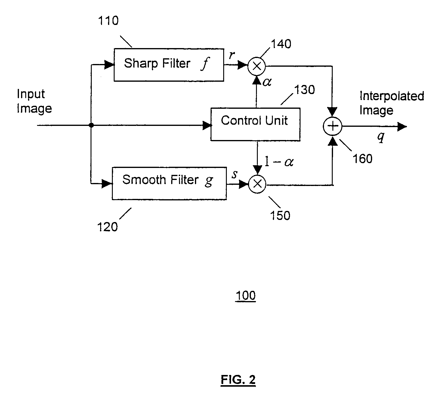
[0022]In one embodiment the present invention provides an image interpolation method and apparatus that utilizes polyphase filters and adaptively selects and / or combines their outputs to achieve a better image interpolation result. As noted, a control strategy is provided to adaptively select or combine the filter output values based on local image high-frequency levels, so that the image interpolation artifacts mentioned above can be avoided.

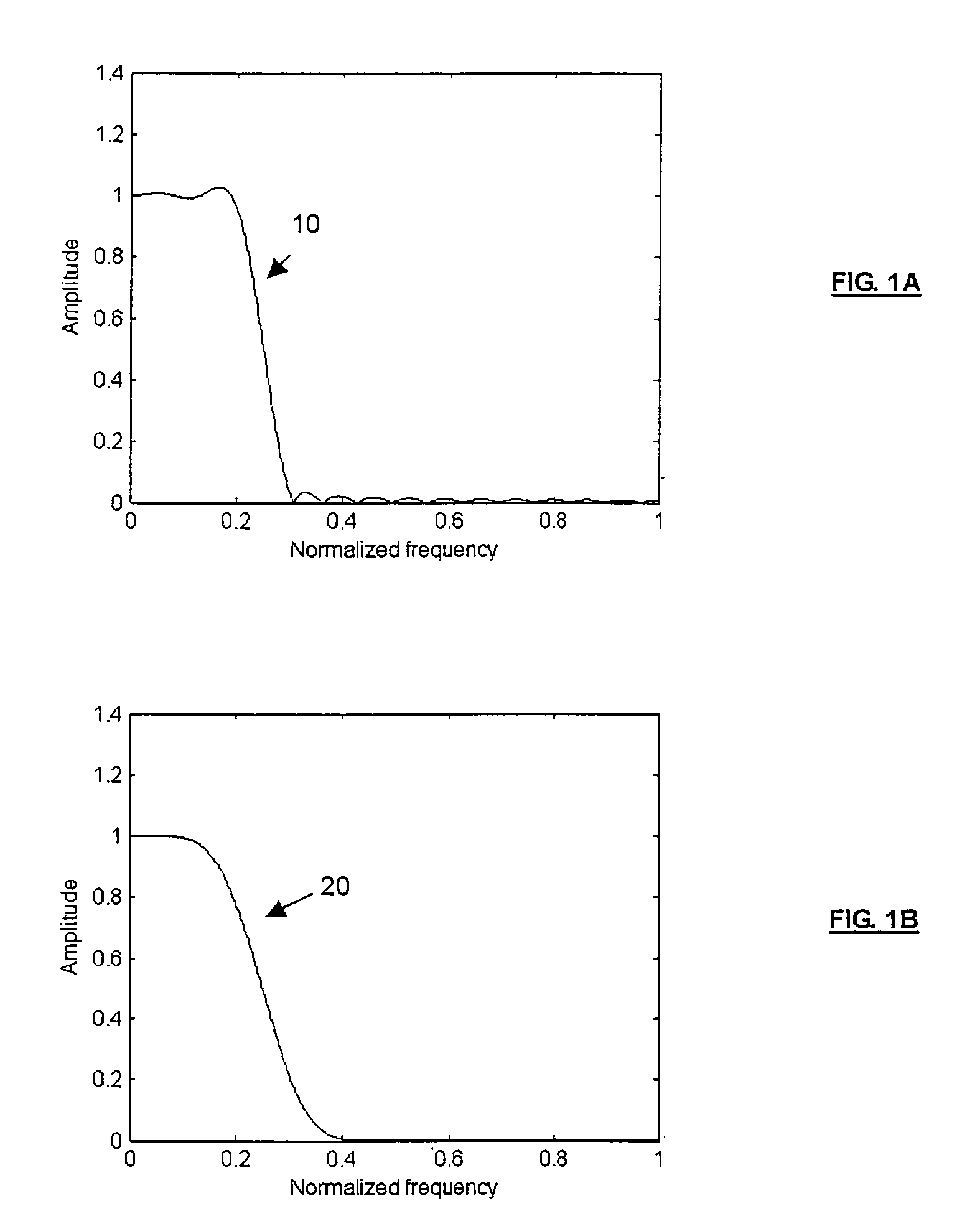
[0023]According to polyphase filter theory for image interpolation, the filters are designed as low pass filters with a cutoff frequency that is directly related to the number of phases of the filter. According to said embodiment of the present invention, the polyphase filters comprise one-dimensional (1D) finite impulse response (FIR) digital filters. Using a one-dimensional filter, a two dimensional image interpolation can be achieved by interpolation along horizontal direction and vertical direction separately.

[0024]As such, an example image...


PUM


Abstract

An interpolation system interpolates image positions in an original image to produce an interpolated output image, wherein the original image is represented by digital input pixel data. A first filter with a sharp interpolation characteristic, that interpolates a selected image position in the image to generate a sharp interpolation output value. A second filter having a smooth interpolation characteristic, that interpolates the selected image position in the image to generate a smooth interpolation output value. A controller that calculates a weighting coefficient for the output of each filter. And, a combiner selectively combines the output values from the filters as a function of the weighting coefficients, to generate an interpolation output value for the selected image position of an interpolated output image.

Description

FIELD OF THE INVENTION[0001]The present invention relates to image interpolation, an in particular to image interpolations using polyphase filters.BACKGROUND OF THE INVENTION[0002]Image interpolation is widely used in applications such as video deinterlacing, video scaling, etc. in digital TV systems. An effective image interpolation technique is important for the overall image quality in a digital TV system. There are image interpolation techniques that generate a sharp image, but they give rise to ringing artifacts around sharp edges. And, existing techniques that generate a smooth image without ringing artifacts, tend to smooth the sharpness of edges and make the edges blurring.[0003]In order to solve those problems, some adaptive image interpolation techniques have been proposed, such as in U.S. Pat. No. 4,468,693, that provide an interpolation method based on a manually operated switch for switching between different interpolation algorithms depending on the type of image being...

Claims


Application Information

Patent Timeline
Patent Type & Authority Patents(United States)
IPC IPC(8): G06K9/32G06K9/36G06K9/40G06F7/38H04N7/01H04N7/015G06T3/40G06T5/00G06T5/20
CPCG06T3/4007G06T5/20G06T5/002G06T5/003G06T2207/10016G06T2207/20192H04N7/015
Inventor WANG, XIANGLINKIM, YEONG-TAEG
Owner SAMSUNG ELECTRONICS CO LTD
Why Eureka
Try Eureka