Pre-connectorized fiber optic cable network interconnection apparatus

a fiber optic cable and interconnection technology, applied in the field of pre-connectorized fiber optic cable network interconnection apparatus, can solve the problems of complex and difficult access to fiber optic adapter cables, and achieve the effects of preventing kinking or sharp bend, facilitating cable access, and preventing damag

Active Publication Date: 2008-06-24
CORNING OPTICAL COMM LLC
View PDF11 Cites 114 Cited by
  • Summary
  • Abstract
  • Description
  • Claims
  • Application Information

AI Technical Summary

Benefits of technology

[0007]In another embodiment, the present invention provides a pre-connectorized interconnection apparatus for mounting within a distribution frame or connector housing. The apparatus includes a housing defining a first portion for fiber optic cable storage and a second portion for fiber optic cable routing to at least one adapter. The first and second portions may be separated by a transition lid, also referred to herein as a “false bottom.” The transition lid may define an opening for transitioning the fiber optic cable from the first portion to the second portion. The length of fiber optic cable is stored and maintained by storage structure affixed to a tray, also referred to herein as the “lid.” The storage tray is slidably and pivotally attached to the apparatus housing. A front portion of the housing includes at least one slot for mounting at least one adapter. In one embodiment, the front portion defines at least one row or column of slots for mounting a plurality of adapters. The front portion may further define mounting fasteners, such as plungers and grommets, for readily and removably mounting the apparatus within a distribution frame, connector housing or other mounting structure. The rear portion of the apparatus defined by the tray includes a port for allowing the fiber optic cable to pass through, a lock mechanism for preventing the tray from being extended when a strong pull in the cable occurs, and an optional handle for pulling out the tray to access the fiber optic cable length. The apparatus may further include a self-locking latch.
[0008]In yet another embodiment, the present invention provides a data center module including at least one LC duplex and / or SC duplex adapter positioned about the front of the module and an MTP connector positioned about the rear of the module. The fiber optic cable within the module is strain relieved to prevent damage caused by exceeding the minimum bend radius in the situation of a strong pull on the cable. A flexible boot is provided about the rear of the module and is retained within a recess defined by the module. The flexible boot may provide strain relief of the cable when inserted into the recess and also prevents kinking or sharp bending in the cable adjacent the module. The module may include any type and length of fiber optic cable capable of providing a link between modules. The fiber optic cable may include any now known of hereinafter devised type of optical fiber including single mode, multimode and bend insensitive types of optical fibers. Fiber optic cable length is accessed by opening the module to access the storage tray. The storage tray may be slid and rotated to a predetermined angle once opened to facilitate cable access. The cable may be manually coiled or un-coiled and deployed as needed. Module sizes may include single wide and double wide versions, among others. Module may be designed to be either left-opened or right-opened in order to have the fiber optic cable exit at the top or bottom of the module. In preferred embodiments, the module requires no tools for access and operation.

Problems solved by technology

Distribution frames are typically used to mount connector housings, terminal blocks and / or main frame connectors, and fiber optic adapter access and cable management is often complex and difficult due to the number of connectors populating a distribution frame.

Method used


Image

  • Pre-connectorized fiber optic cable network interconnection apparatus
  • Pre-connectorized fiber optic cable network interconnection apparatus
  • Pre-connectorized fiber optic cable network interconnection apparatus

Examples


Embodiment Construction

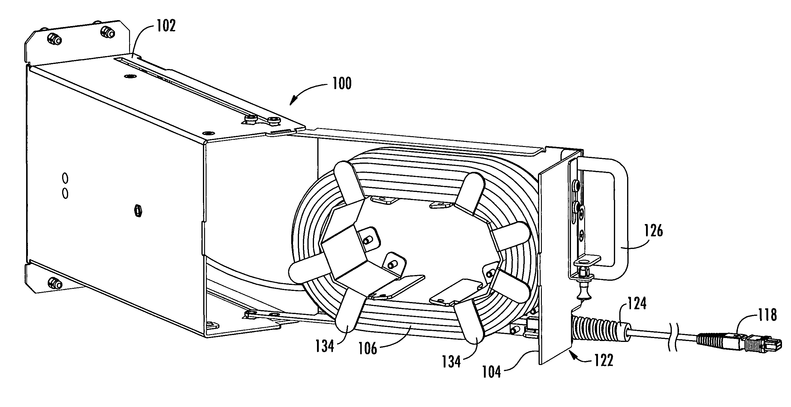
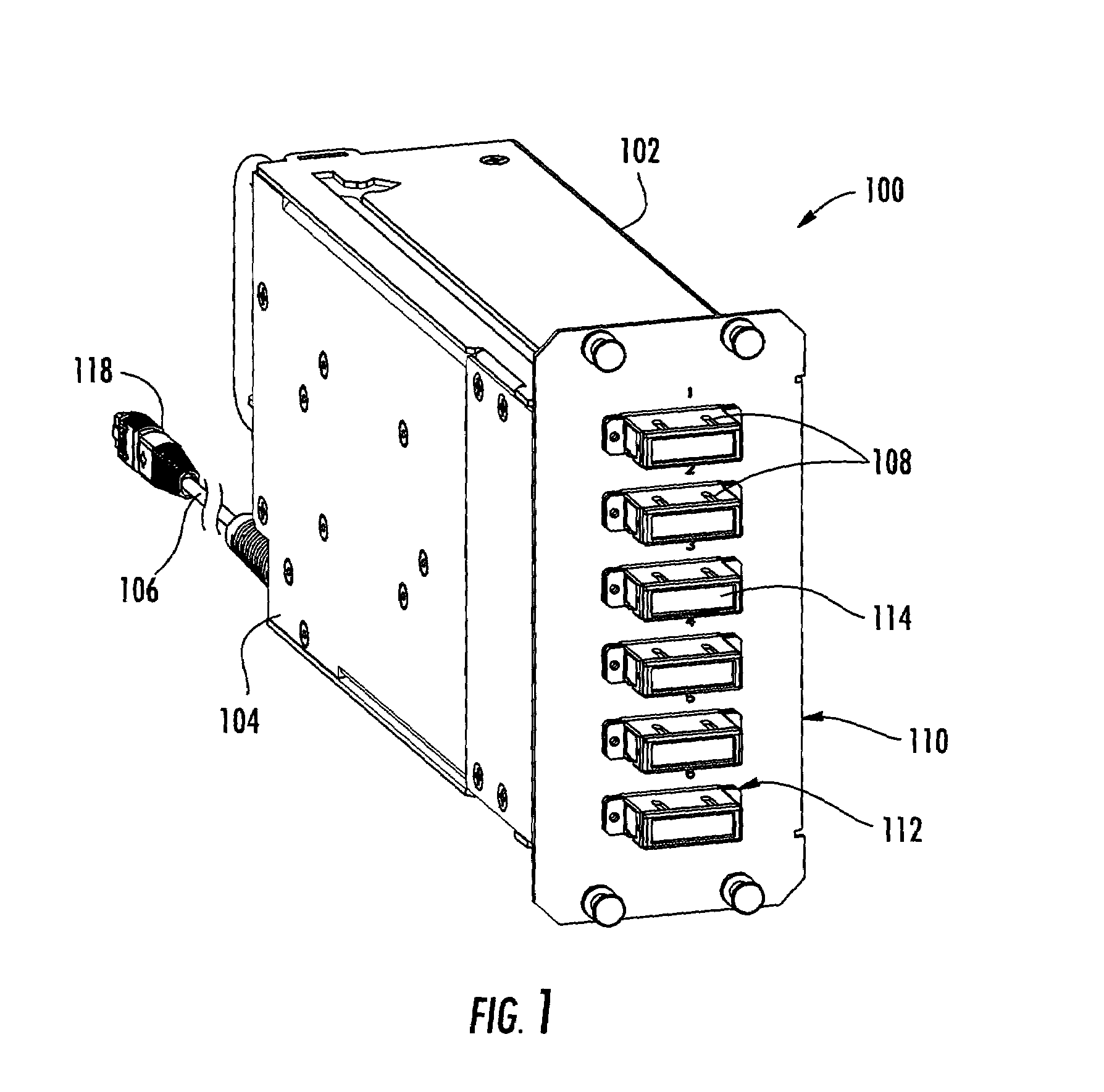
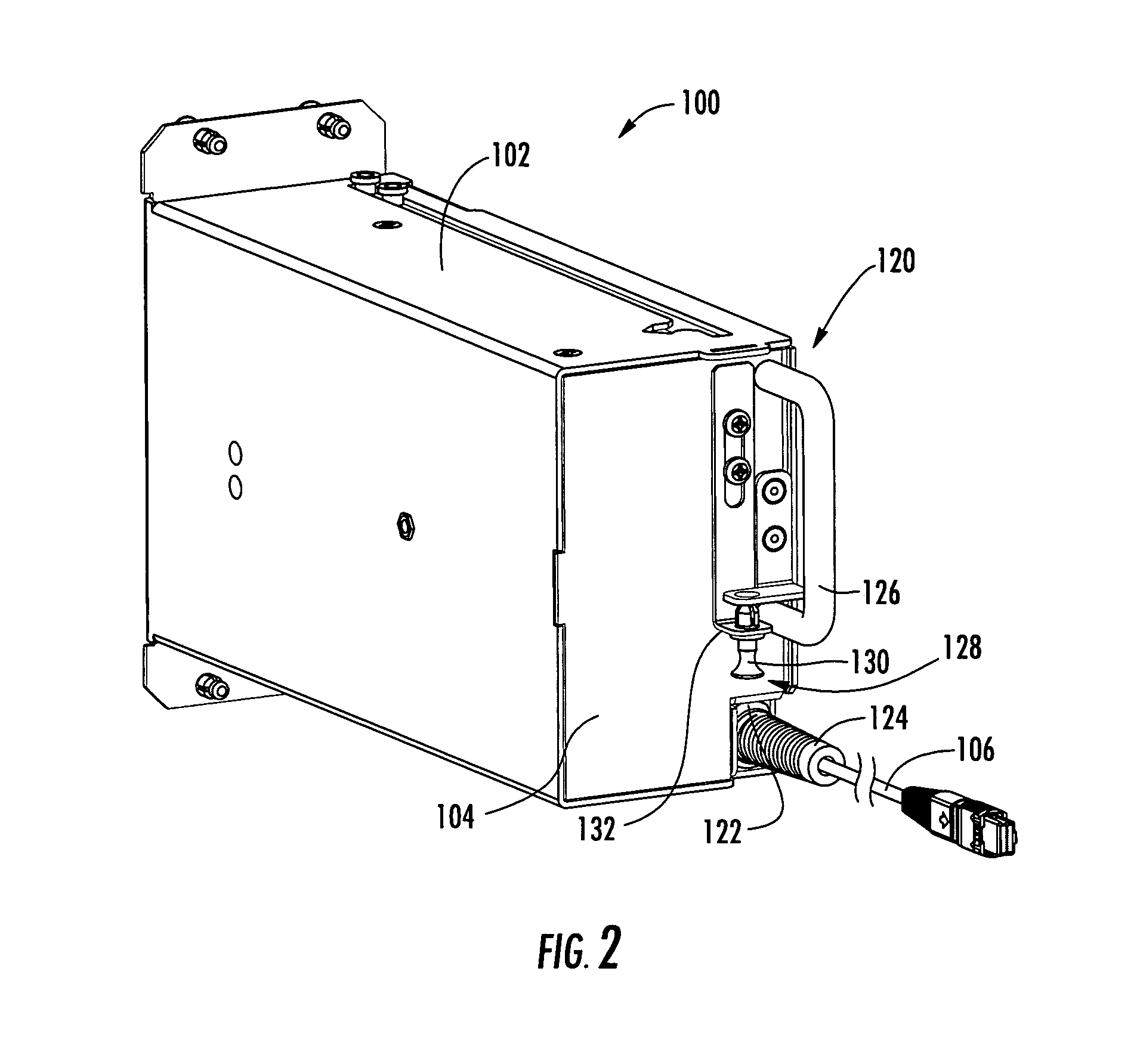
[0017]Reference will now be made in detail to the preferred embodiments of the present invention, examples of which are illustrated in the accompanying drawings. Whenever possible, like reference numbers will be used to refer to like components or parts. Although specific data center network apparatus are shown and include duplex SC or LC connector adapters, it is envisioned that other apparatus configurations including any adapter, connector or cable type may be incorporated without departing from the spirit and scope of the present invention. Although the present invention is primarily described for use in a data center, the present invention may be deployed in any network environment in which is it desired to provide a pre-connectorized fiber optic link or interconnection point. The data center apparatus may be a stand-alone unit or may be mounted within a connector housing distribution frame of other structure.

[0018]Referring to FIGS. 1-8, the data center apparatus 100, also ref...


PUM


Abstract

A pre-connectorized network interconnection apparatus including a housing defining at least one opening for mounting at least one adapter therein, a cable storage tray movably attached to the housing movable between an opened position and a closed position for cable access, and a predetermined length of pre-connectorized fiber optic cable maintained on the storage tray, wherein a first end of the fiber optic cable terminates in at least one connector routed to the at least one connector adapter within the apparatus and a second end of the fiber optic cable terminates in at least one connector that is routed to a predetermined location within a fiber optic network. A data center network apparatus for linking separated fiber optic connection points using a length of pre-connectorized fiber optic cable.

Description

BACKGROUND OF THE INVENTION[0001]1. Field of the Invention[0002]The present invention relates generally to an apparatus for storing and maintaining fiber optic cable and providing a link for future deployment within a data center or other optical network environment, and more specifically, to a fiber optic network interconnection apparatus that allows a technician to coil and uncoil a desired length of pre-connectorized fiber optic cable for future or re-installation from the rear side of an installed apparatus.[0003]2. Technical Background of the Invention[0004]Fiber optic networks are being developed to deliver voice, video, and data transmissions to subscribers over both private and public networks. These fiber optic networks often include separated connection points at which it is necessary to link optical fibers in order to provide “live fiber” from one connection point to another connection point. Often times, these separated connection points are found within different distri...

Claims


Application Information

Patent Timeline
Patent Type & Authority Patents(United States)
IPC IPC(8): G02B6/00
CPCG02B6/4453G02B6/4455
Inventor UGOLINI, ALAN W.BARNES, RAY S.DENNIS, ROBERT W.JUAREZ, ELMER MARIANOLOPEZ SANCHEZ, MANUEL ALEJANDRO
Owner CORNING OPTICAL COMM LLC
Why Eureka
Try Eureka