
Method and device for locating the position, on the right or on the left, of a wheel of a vehicle

a technology for locating the position and the left side of the vehicle, which is applied in the direction of tyre measurement, hardware monitoring, registering/indicating, etc., can solve the problem that the overall cost of sourcing and fitting of two magnetic sensors is lower than that of one antenna, and achieve the effect of reducing the disadvantage and reducing the overall cost of sourcing and fitting

Active Publication Date: 2008-06-24
CONTINENTAL AUTOMOTIVE FRANCE
View PDF6 Cites 25 Cited by
  • Summary
  • Abstract
  • Description
  • Claims
  • Application Information

AI Technical Summary

Benefits of technology

[0012]The present invention is aimed at alleviating the disadvantage associated with the length of the right / left location procedure of the second technique described hereinabove and its main objective is to provide a right / left location procedure that is very efficient in terms of responsiveness and in addition, to implement it, requires hardware the overall cost of sourcing and fitting of which is lower than the overall cost of an antenna.
[0020]According to this principle, the invention leads to very quick location of the wheel position, on the right / on the left, which location is in fact obtained after a few revolutions of the wheel. In addition, the overall cost (sourcing and fitting) of two magnetic sensors is lower than that of one antenna.
[0024]For its part, the invention consists in using two very low-price sensors, the results of the measurements of which can be used very quickly right from the first few revolutions of the wheel of the vehicle.
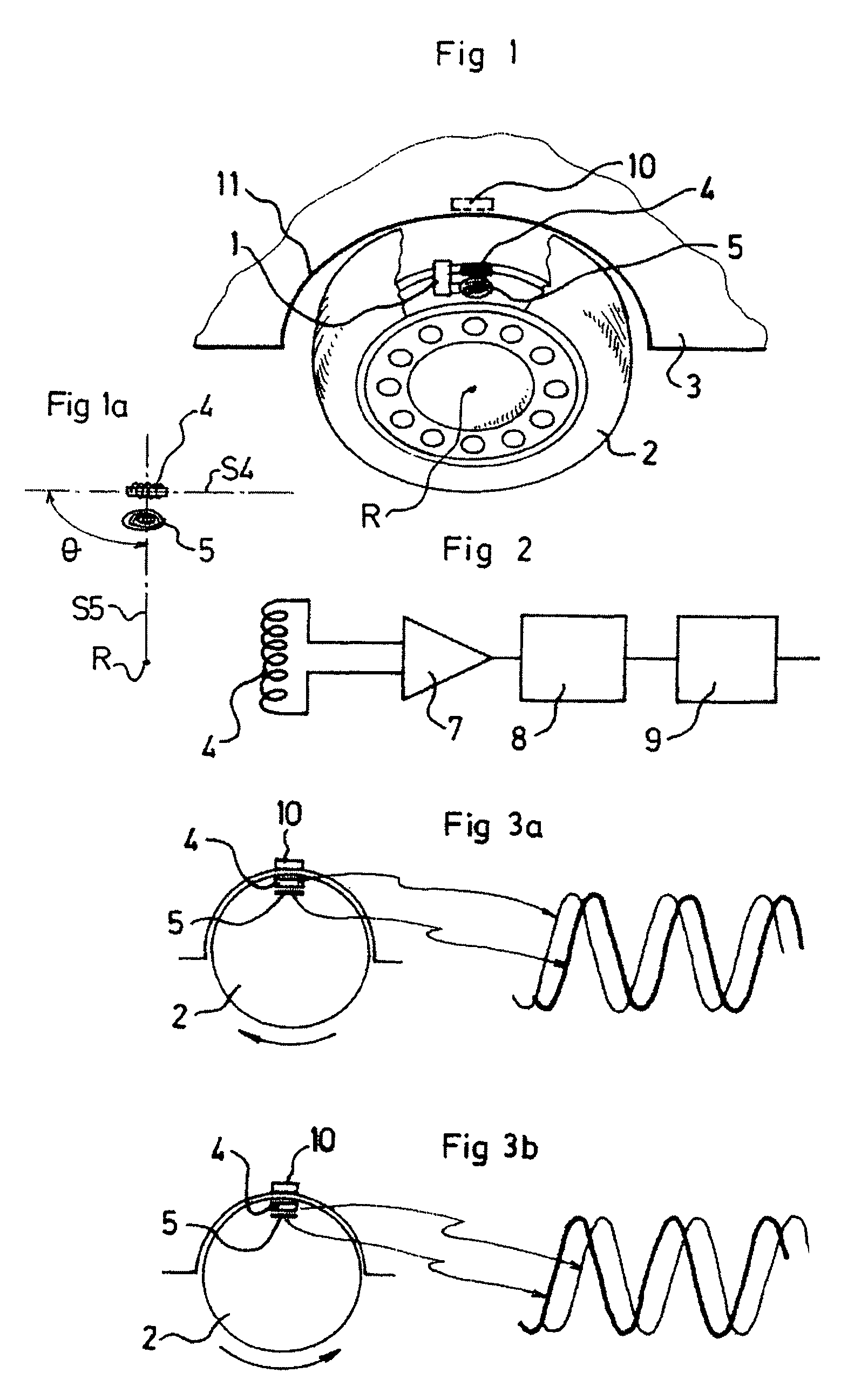
[0027]Furthermore, with a view to increasing the sensitivity of the method according to the invention and advantageously, the cyclic signal representative of the variations in the values of the magnetic field as detected by each magnetic sensor is amplified and shaped in such a way as to obtain a periodic signal of squarewave shape as the vehicle moves along.

Problems solved by technology

In addition, the overall cost (sourcing and fitting) of two magnetic sensors is lower than that of one antenna.

Method used


Image

  • Method and device for locating the position, on the right or on the left, of a wheel of a vehicle
  • Method and device for locating the position, on the right or on the left, of a wheel of a vehicle

Examples


Embodiment Construction

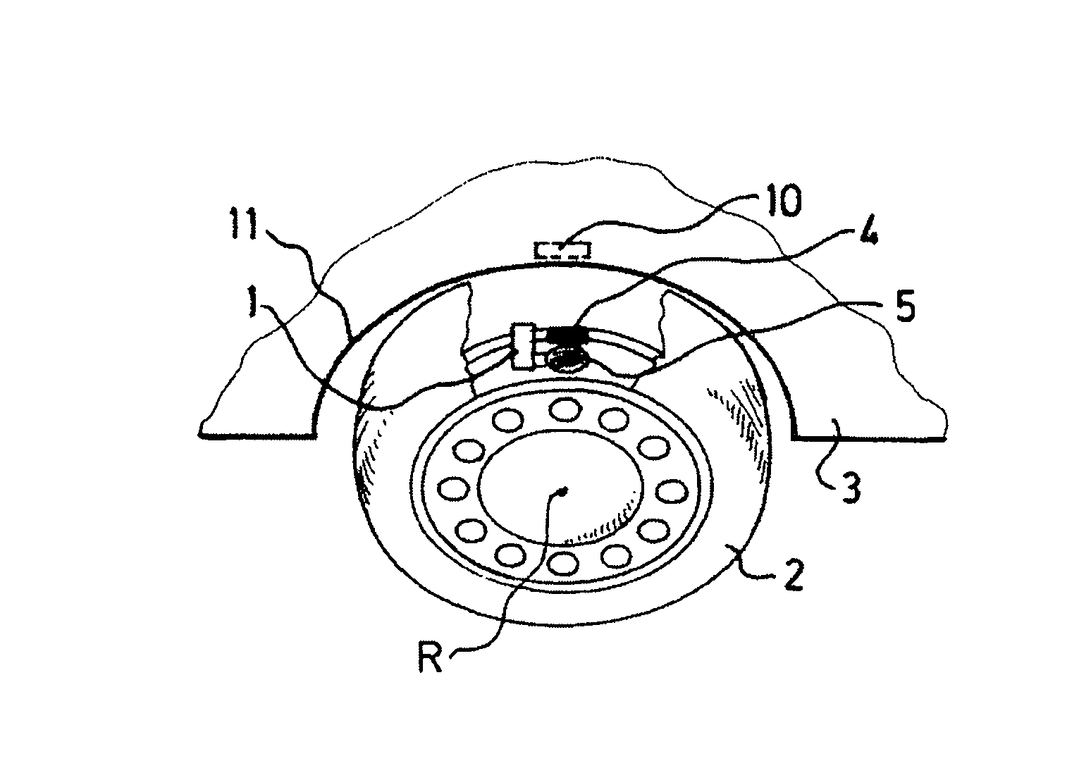
[0043]The location device according to the invention depicted by way of example in FIG. 1 is intended to locate the position of a wheel as being on the right or on the left side of a vehicle.

[0044]This location device is more specifically intended to be installed on vehicles equipped with a monitoring system comprising electronic units 1 mounted on each of the wheels 2 of the vehicles 3, incorporating sensors dedicated to measuring parameters such as the pressure and / or the temperature of the tires with which these wheels 2 are equipped, and intended to inform the driver of any abnormal variation in the parameter measured.

[0045]This location device firstly comprises two magnetic sensors 4, 5 designed to be able to be incorporated into the same electronic unit 1 and arranged in such a way that their respective axes of maximum sensitivity S4, S5 lie in the same plane perpendicular to the axis of rotation of the wheel 2 and are offset from one another by a predetermined angle θ=90°.

[00...


PUM


Abstract

A method and device for locating the position, on the right or on the left, of a vehicle wheel. The wheel is equipped with two magnetic sensors having axes of maximum sensitivity lying in a plane that is secant to the axis of rotation of the wheel and which are offset from one another in this secant plane by a predetermined angle θ. As the vehicle moves in a given travel direction, a signal generated by the variation in a magnetic field is measured at the terminals of each of the magnetic sensors to deliver two periodic signals phase-shifted from one another by an angular value equal to (+ or −) θ, this phase shift is used to determine the direction of wheel rotation, and from such direction and the travel direction, the location, on the right or on the left, of the wheel is deduced.

Description

BACKGROUND OF THE INVENTION[0001]The invention relates to a method and a device for locating the position of a wheel with respect to the right or on the left side of a vehicle.DESCRIPTION OF THE RELATED ART[0002]Motor vehicles are increasingly possessing, for safety purposes, monitoring systems comprising sensors mounted on each of the wheels of the vehicle, these sensors being dedicated to measuring parameters, such as the pressures or temperatures of the tires with which these wheels are equipped, and intended to inform the driver of any abnormal variation in the parameter measured.[0003]These monitoring systems are conventionally provided with a sensor mounted on each of the wheels of the vehicle and comprising a microprocessor and a radiofrequency emitter (or RF emitter) and with a central unit for receiving the signals emitted by the emitters, comprising a computer incorporating a radiofrequency receiver (or RF receiver) connected to an antenna.[0004]One of the problems that su...

Claims


Application Information

Patent Timeline
IPC IPC(8): G01M17/00G01M17/02G06F19/00G06F7/00
CPCB60C23/0416B60C23/00B62D15/02
Inventor ALLARD, PIERRE-YVESDULAC, GILLES
Owner CONTINENTAL AUTOMOTIVE FRANCE
Learn More