Crop cutting header with speed control of driven element using valve profiling

a technology of profiling and driving elements, applied in the direction of computation using non-denominational number representation, analog and hybrid computing, application, etc., can solve the problems of control system not being able to dynamically determine how to correct the speed, and the control module not knowing how much of a pwm control signal is required, so as to maintain a degree of control

Active Publication Date: 2008-06-24
MACDON INDS
View PDF11 Cites 26 Cited by
  • Summary
  • Abstract
  • Description
  • Claims
  • Application Information

AI Technical Summary

Problems solved by technology

However, if the speed sensor fails, the control system has no way to dynamically determine how to correct the speed when a change is required.
The operator could still input a different set point, but the control module would not know how much of a PWM control signal is required to maintain the desired set point.

Method used


Image

  • Crop cutting header with speed control of driven element using valve profiling
  • Crop cutting header with speed control of driven element using valve profiling
  • Crop cutting header with speed control of driven element using valve profiling

Examples


Embodiment Construction

[0034]Reference is made to co-pending application Ser. No 11 / 116,417 filed Apr. 28, 2005 by the present assignees which discloses and claims some of the features described hereinafter.

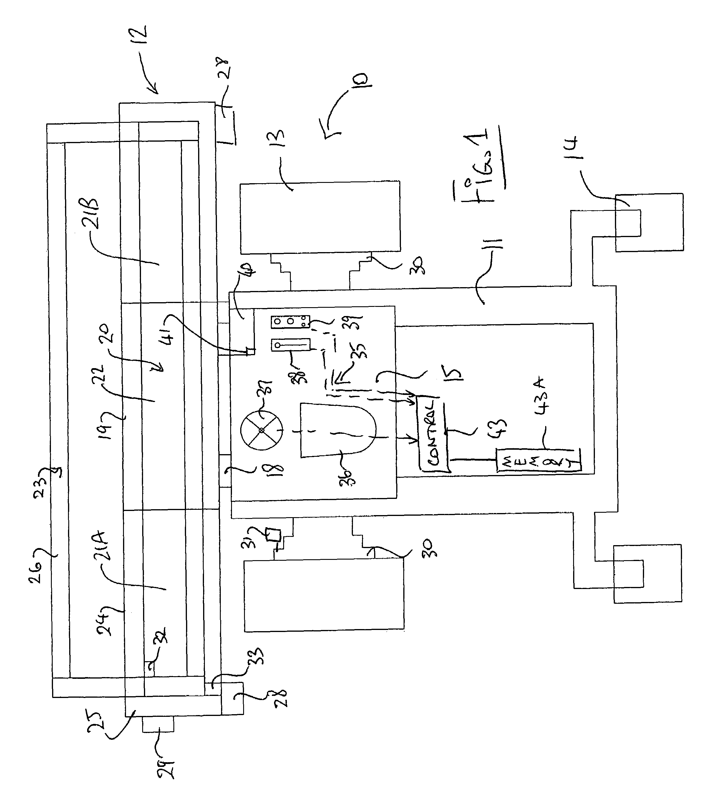
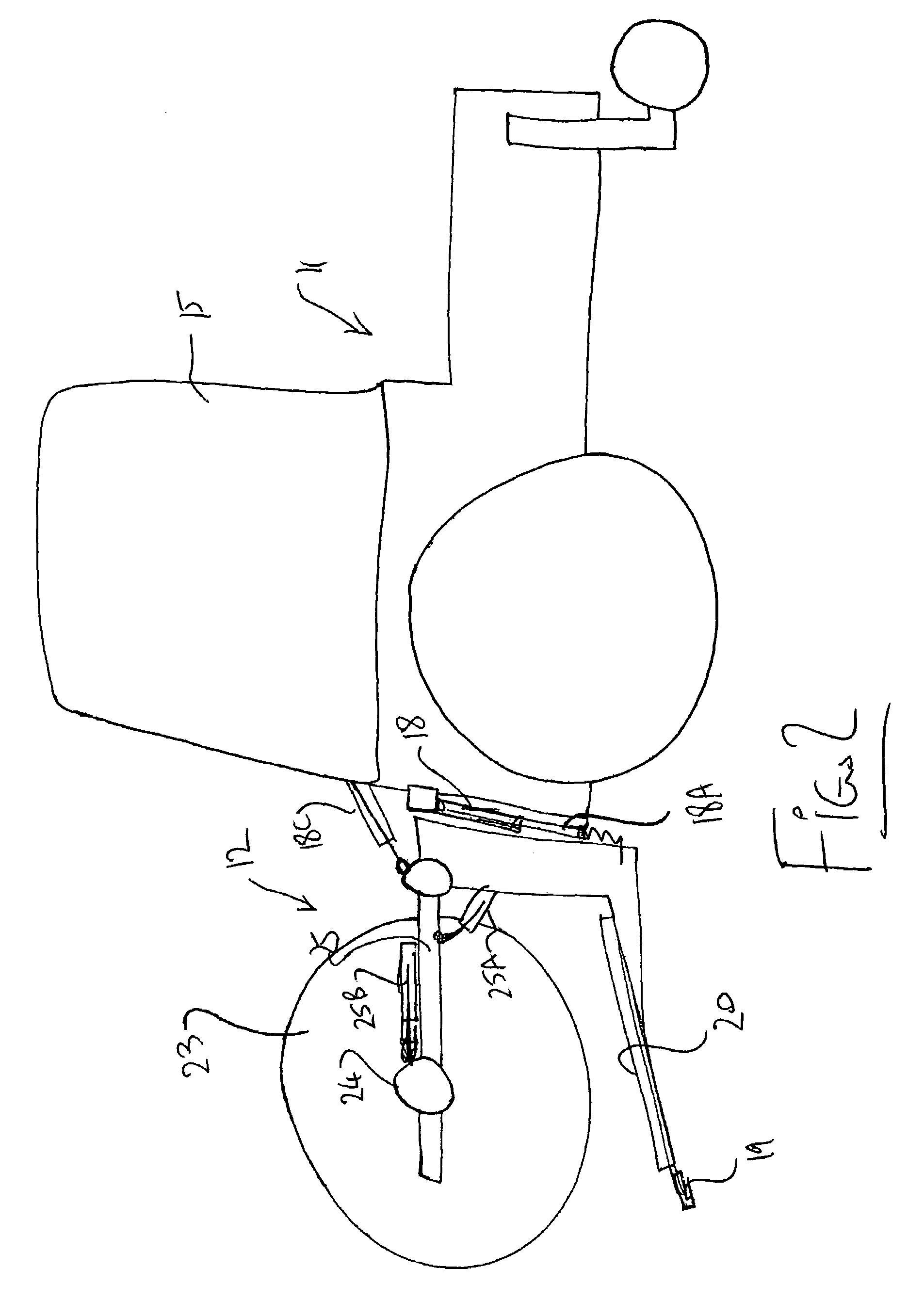
[0035]In FIG. 1 is shown a swather generally indicated at 10 which includes a tractor 11 and a header 12. The swather tractor is preferably of the type which includes driven front wheels 13 and trailing rear castor wheels 14 with a cab 15 over the front wheels and an engine and drive arrangement 16 at the rear wheels. The tractor includes header support members 18 at the forward end which mount the header in front of the tractor for movement across the ground for cutting standing crop.

[0036]The header support members are shown only schematically but generally include a pair of side arms 18A and 18B each adjacent a respective wheel of the tractor and extending forwardly to a respective location on the header. The arm height can be adjusted to raise and lower the header at that position. An adjustable ce...


PUM


Abstract

In a swather formed by a tractor and attached header for cutting standing crop to form a swath, reel speed and optionally draper speed are controlled relative to ground speed by a control system including a manually operable input and display available to the operator. The control system acts to calibrate” the control output so that the control module has a secondary reference point as to how the PWM valve should function in the event of a speed sensor failure. Instead of using the speed sensor signal as a reference, the control system now compares the set point with the stored table (which may in one example provide 256 values) containing the PWM voltage / current values. These values correspond to a set of actual speed sensor values taken during the profiling procedure, plus extrapolated values equalling 256 points.

Description

[0001]This invention relates to a crop cutting header with an operator controlled system for maintaining speed of a driven element of the header.BACKGROUND OF THE INVENTION[0002]Crop harvesting machines, like windrowers and combines use various driven elements to effect the cutting and harvesting systems including a cutting system and commonly a reel. The speed of the cutting system is generally variable to accommodate different crop conditions and different harvesting speeds. The reel is used to lift crop that is down & lodged so the cutting mechanism has good access to the plant (not leaving any seeds or desirable plant material behind) and to push the crop into the header for conveying to the windrow discharge. For maximum efficiency (effectively raise the plants, minimize seed shatter, minimize wear on mechanical parts and minimize power required to drive the reel), it is highly desirable that the reel run at the right speed and that the operator has full control of the reel spe...

Claims


Application Information

Patent Timeline
Patent Type & Authority Patents(United States)
IPC IPC(8): G06F7/70G06F19/00G06G7/00G06G7/76
CPCA01D57/20
Inventor MACGREGOR, DONDUNN, JAMES THOMAS
Owner MACDON INDS
Why Eureka
Try Eureka