
Transmitted-light base for a microscope, and method for regulating the illumination intensity of a transmitted-light base

a technology of transmitted light and microscope, which is applied in the direction of instruments, lighting and heating apparatus, free standing, etc., can solve the problems of difficult comparison of results in different illumination modes, changes in settings regarding resolution and contrast of microscopes are overlain by changes in brightness, and the device of this kind as known from the lamp housing of fiber illumination system is not implemented in the transmission light base having an integrated illumination system, so as to achieve controllable illumination intensity

Inactive Publication Date: 2008-07-01
LEICA INSTR SINGAPORE PTE
View PDF11 Cites 10 Cited by
  • Summary
  • Abstract
  • Description
  • Claims
  • Application Information

AI Technical Summary

Benefits of technology

The present invention provides a transmitted-light base for zoom microscopes with an integrated light source that allows for controllable illumination intensity and color temperature. This is achieved through a mechanical brightness regulator that can be adjusted without changing the electrical power level of the light source. The brightness regulator can be placed close to the reflector lamp or the collector lens of the light source. The invention also includes a louver with adjustable slats that can be used to control the brightness of the transmitted-light base. The slats can be made of metal or partially transparent materials, and the louver can be opened and closed manually or with an electronically controlled positioning member. The invention allows for constant and specific brightness adjustments during zoom operation, and can be used in a variety of light sources.

Problems solved by technology

A color temperature shift of this kind modifies the perceived color of the object image, thus making it difficult to compare the results in different illumination modes.
The teaching of this document is based on the problem that changes in settings regarding the resolution and contrast of the microscope are overlain by a change in the brightness of the microscope image.
A device of this kind as known from lamp housings for fiber illumination systems is not, however, implemented in transmitted-light bases having an integrated illumination system.

Method used


Image

  • Transmitted-light base for a microscope, and method for regulating the illumination intensity of a transmitted-light base
  • Transmitted-light base for a microscope, and method for regulating the illumination intensity of a transmitted-light base
  • Transmitted-light base for a microscope, and method for regulating the illumination intensity of a transmitted-light base

Examples


Embodiment Construction

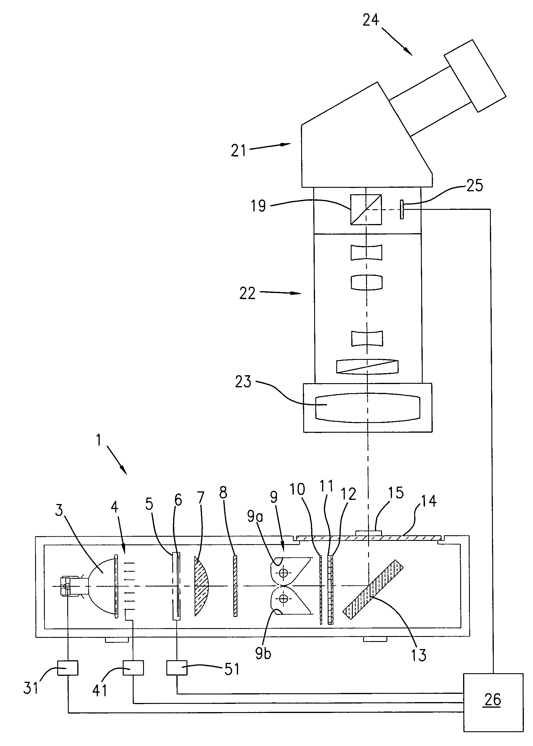
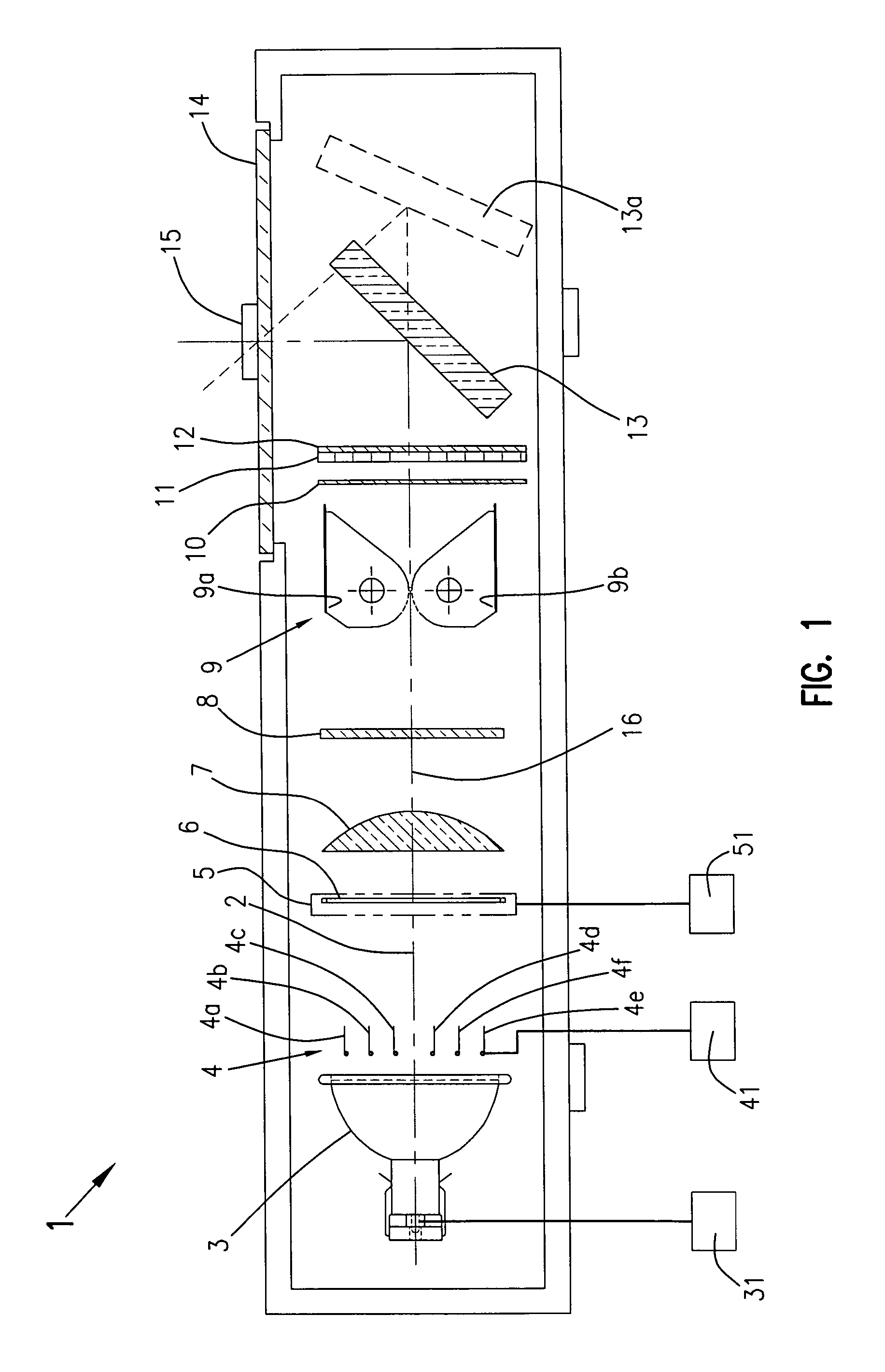
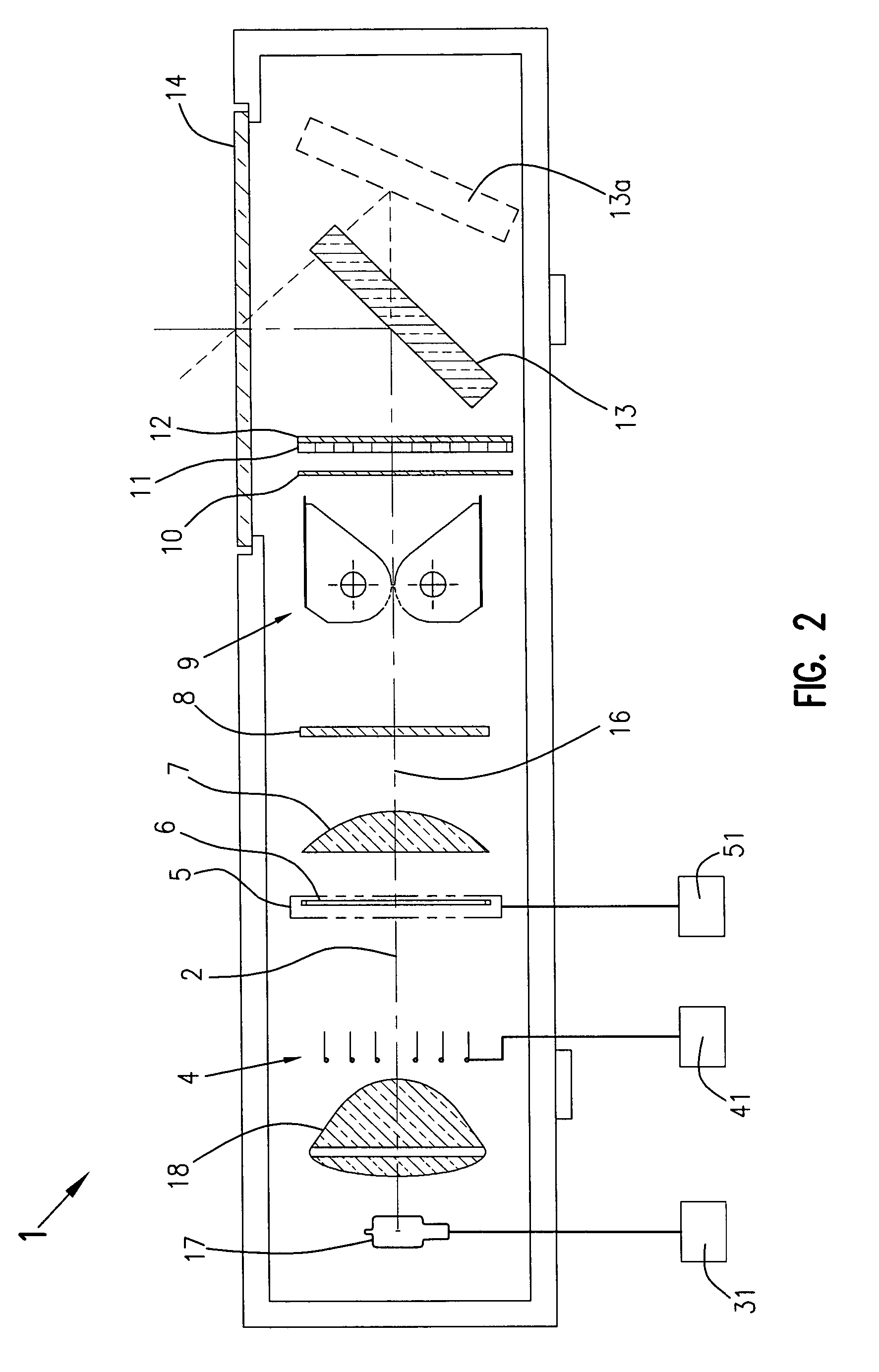
[0050]FIG. 1 shows transmitted-light base 1 according to the present invention. The optical axis is labeled 2. A reflector lamp 3, constituting a light source, divergently emits light of a specific spectral composition. With the aid of electrical power regulation system 31, usually a voltage regulator, the light output of the lamp can be regulated in known fashion, manually or by an electronically controlled positioning member.

[0051]A louver 4, constituting a mechanical brightness regulator, is arranged close to the reflector exit. In this arrangement, the illumination aperture and the illuminated field of object plane 14 remain substantially unchanged by the mechanical brightness regulator. Louver 4 is to be actuated either manually via a lever (not depicted), or by an electronically controlled positioning member 41.

[0052]Arranged after the louver, as a means for generating a specified spectral intensity distribution, is a filter insert 5 with which a color conversion filter 6, e.g...


PUM


Abstract

The invention relates to a transmitted-light base (1) for illuminating an object (15) for imaging through a zoom microscope (21), the transmitted-light base (1) comprising an integrated light source (3) having an associated electrical power regulation system (31) for generating a suitable radiation flux, and means (5, 6), capable of being added downstream, for generating a specified spectral intensity distribution. To allow compensation for brightness changes of low dynamic range, such as those occurring in particular during zooming, a continuously controllable mechanical brightness regulator (4) is proposed which is activatable by means of an associated adjustment device (41) in such a way that the illumination intensity of the transmitted-light base (1) is controllable with no change in the spectral intensity distribution. The brightness regulator (4) is arranged close to the light exit side of a reflector lamp (3) used as the light source, or, when a lamp (17) and collector lens (18) are used as the light source, close to the collector lens (18).

Description

CROSS REFERENCE TO RELATED APPLICATIONS[0001]This application claims priority of German Patent Application No. 10 2004 056 685.2, filed on Nov. 24, 2004, which is incorporated by reference herein.FIELD OF THE INVENTION[0002]The invention relates to a transmitted-light base (transmitted illumination device) having an integrated light source for microscopes, in particular for those having continuously variable magnification (called “zoom microscopes” for short), such as high-power stereo zoom microscopes, and to a method for regulating the illumination intensity of a transmitted-light base. More precisely, the invention relates to a transmitted-light base for illuminating an object for imaging through a zoom microscope, that transmitted-light base comprising a light source having an associated electrical power regulation system for generating a suitable radiation flux, and means, capable of being added downstream, for generating a specified spectral intensity distribution. The method ...

Claims


Application Information

Patent Timeline
Patent Type & Authority Patents(United States)
IPC IPC(8): G02B21/06
CPCG02B21/086
Inventor ROTTERMANN, RUEDIKOPF, PATRICKGESCHWENTNER, OTTOZIMMER, KLAUS-PETER
Owner LEICA INSTR SINGAPORE PTE
Learn More