Ink jet printing apparatus and ink jet printing method
a printing apparatus and ink jet technology, applied in the direction of printing, typewriters, spacing mechanisms, etc., can solve the problems of uneven printing image density, ink droplet , inability to permeate well through, and inability to fix well, etc., to suppress, and reduce the unevenness of time differen
- Summary
- Abstract
- Description
- Claims
- Application Information
AI Technical Summary
Benefits of technology
Problems solved by technology
Method used
Image
Examples
embodiment 1
[0094]FIG. 10 is a flow chart showing a procedure of printing operation according to a first embodiment of the present invention.
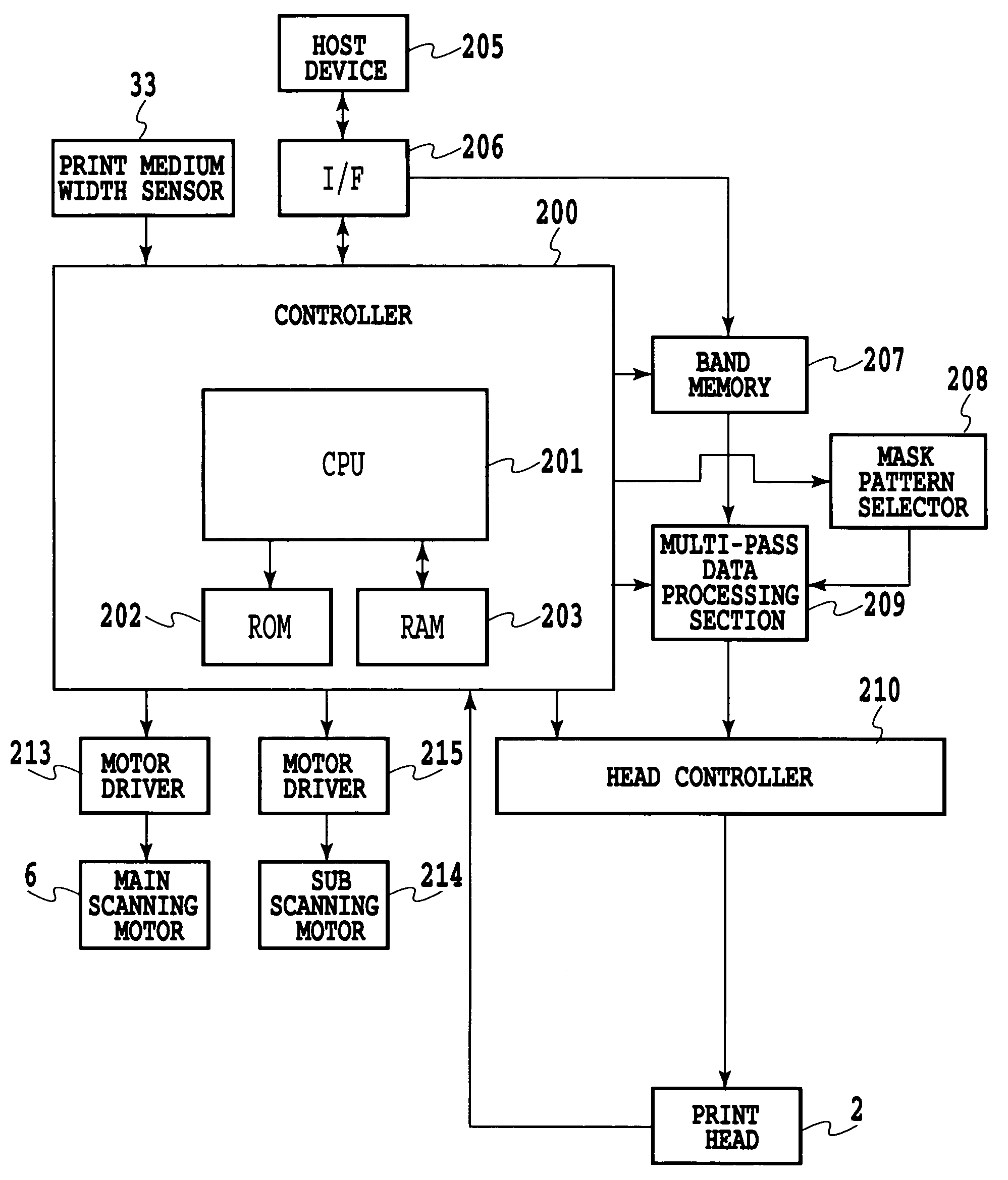
[0095]In FIG. 10, the host device 205 first inputs a print instruction command and print data to the CPU 201 via the interface 206. The CPU 201 then writes print data for one band in the band memory 207 (step S501). Then, the multi-pass data processing section 209 reads all the image data for one band from the band memory 207.
[0096]Then, the CPU 201 obtains information on the width of a print medium used for printing. The CPU 201 then determines the number of passes in multi-pass printing on the basis of the information obtained on the width of the print medium (step S503). More specifically, the CPU 201 references a table described later in detail in FIG. 11 on the basis of the information obtained on the width of the print medium. The CPU 201 thus selects a 2- or 8-pass multi-pass print mode as a print mode. The information on the width of the print medi...
embodiment 2
[0118]In the present embodiment, the feeding of the print medium in the bidirectional printing is controlled to avoid varying the print time difference between the opposite ends of the scan area. The time difference unevenness is thus suppressed.
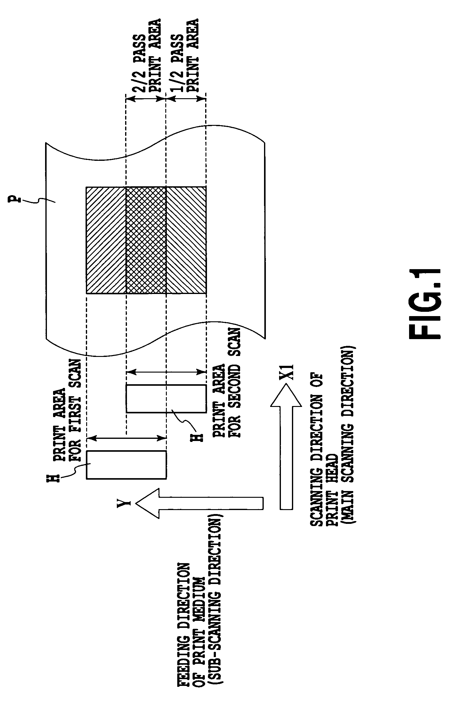
[0119]FIG. 15 is a diagram illustrating a printing method used if the fed amount is changed (this change will hereinafter be referred to as special feeding) in the 2 pass printing according to a second embodiment of the present invention. FIG. 15 shows the relationship between the position of the print head H and the print area of an image printed on the print medium P.
[0120]In FIG. 15, an image or the like is printed in a print area for the first scan by causing the print head H to eject the ink on the basis of print data while moving the print head H in the main scanning direction (the direction of the arrow X1). The present embodiment performs control such that after printing by a forward scan, the print medium is not fed before a backwar...
embodiment 3
[0126]In the present embodiment, the time difference unevenness is suppressed by selecting the scan speed of the print head, that is, the movement speed of the carriage during printing, depending on the width of the print medium.
[0127]FIG. 19 is a diagram showing the evaluation of images for the relationship between the width of the print medium and the occurrence of time difference unevenness observed if the movement speed of the carriage is changed. A five-ranking sensory evaluation similar to that used in FIG. 14 is used as an evaluating method. Evaluation is made for two cases of 25 inch / sec and 50 inch / sec. As is apparent from FIG. 19, with any print medium width, the print time difference decreases at the higher carriage speed, that is, 50 inch / sec. As a result, the time difference unevenness can be suppressed.
[0128]In the print control according to the present embodiment, in the step S503 of the process in FIG. 10, shown in connection with the first embodiment, the width of t...
PUM
 Abstract
Description
Claims
Application Information
 - R&D
- Intellectual Property
- Life Sciences
- Materials
- Tech Scout
- Unparalleled Data Quality
- Higher Quality Content
- 60% Fewer Hallucinations
Browse by: Latest US Patents, China's latest patents, Technical Efficacy Thesaurus, Application Domain, Technology Topic, Popular Technical Reports.
© 2025 PatSnap. All rights reserved.Legal|Privacy policy|Modern Slavery Act Transparency Statement|Sitemap|About US| Contact US: help@patsnap.com


