Ink jet printing apparatus and ink jet printing method

a printing apparatus and ink jet technology, applied in the direction of printing, typewriters, spacing mechanisms, etc., can solve the problems of ink droplets , ink droplets , inability to permeate well through, and inability to fix well, etc., to achieve the effect of sharply increasing the processing load or the time required for processing

Inactive Publication Date: 2005-05-19
CANON KK
View PDF3 Cites 11 Cited by
  • Summary
  • Abstract
  • Description
  • Claims
  • Application Information

AI Technical Summary

Benefits of technology

[0023] It is an object of the present invention to provide an ink jet printing apparatus and an ink jet printing method which can suppress, without sharply increasing a processing load or the time required for processing, time difference unevenness resulting from a print time difference if printing is based on a bidirectional multi-pass system, even for a large-sized sheet ink jet printing apparatus that prints relatively large-sized sheets.

Problems solved by technology

This may lead to the uneven density of the print image (hereinafter also referred to as time difference unevenness).
However, the ink droplet 101b does not permeate well through or is not fixed well to the area in which the ink droplet 101a has already been fixed.
This is markedly perceived as time difference unevenness.
Of course, similar time difference unevenness may occur in multi-pass printing with three passes or more.
However, the above time difference unevenness occurs during the (k+1) / m pass in accordance with the manner in which the ink permeates and is fixed.
This density unevenness affects the final time difference unevenness of that area.
For multi-pass printing with three or more passes, the final time difference unevenness on the completion of the printing creates a problem, similarly to the time difference unevenness during the scan.
The above time difference unevenness problem is significant in a printing apparatus that prints large-sized sheets.
Consequently, there is a larger difference in density between these areas, resulting in the remarkable occurrence of time difference unevenness.
Therefore, the time difference unevenness is a particularly serious problem for large-sized sheet ink jet printing apparatuses that can print relatively large-sized sheets.
This results in the need for an extra time for processing.
In particular, for an image to be printed on a large-sized sheet ink jet printing apparatus has an enormous amount of print data, the above problem is more serious.

Method used


Image

  • Ink jet printing apparatus and ink jet printing method
  • Ink jet printing apparatus and ink jet printing method
  • Ink jet printing apparatus and ink jet printing method

Examples


embodiment 1

[0094]FIG. 10 is a flow chart showing a procedure of printing operation according to a first embodiment of the present invention.

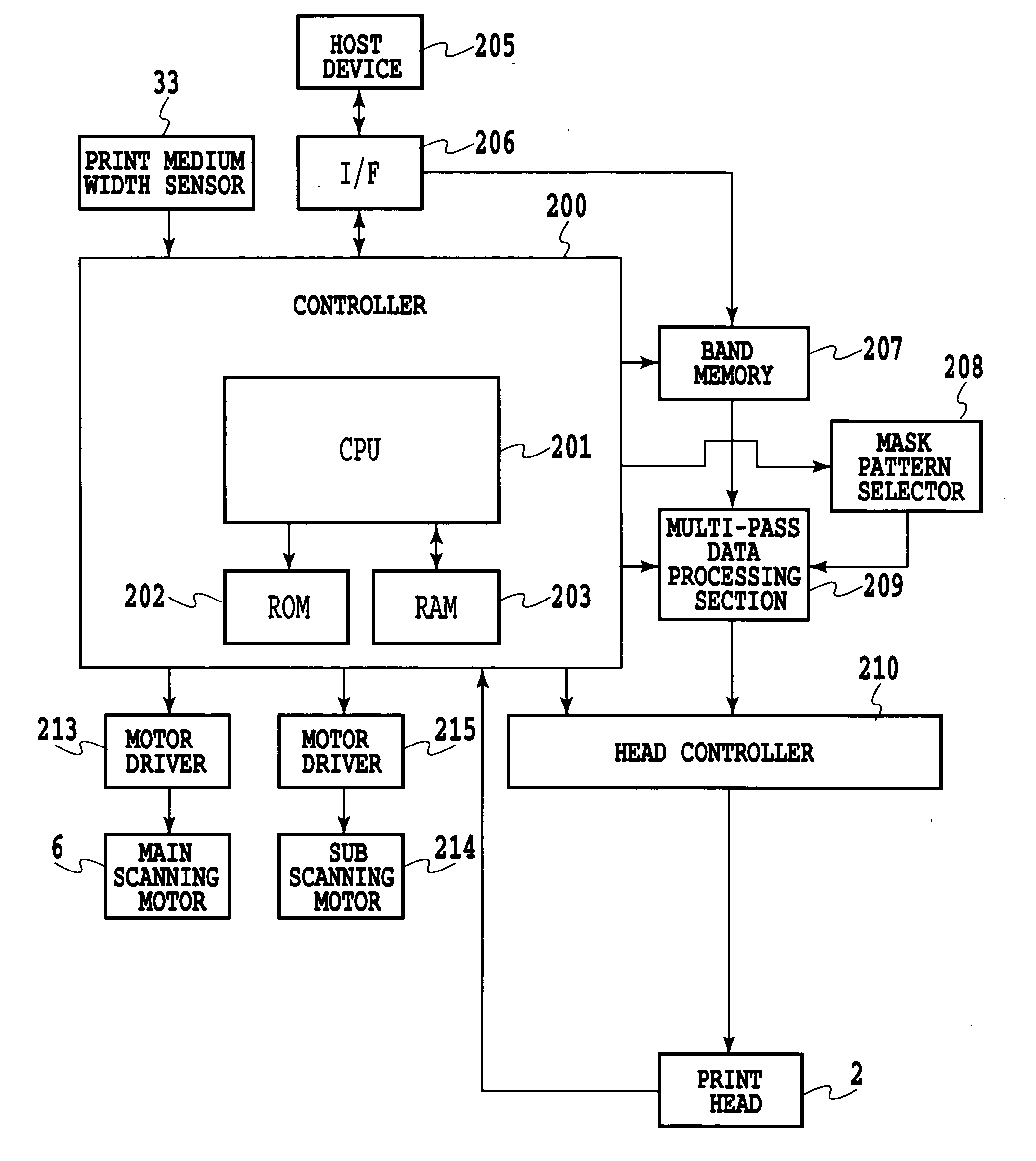
[0095] In FIG. 10, the host device 205 first inputs a print instruction command and print data to the CPU 201 via the interface 206. The CPU 201 then writes print data for one band in the band memory 207 (step S501). Then, the multi-pass data processing section 209 reads all the image data for one band from the band memory 207.

[0096] Then, the CPU 201 obtains information on the width of a print medium used for printing. The CPU 201 then determines the number of passes in multi-pass printing on the basis of the information obtained on the width of the print medium (step S503). More specifically, the CPU 201 references a table described later in detail in FIG. 11 on the basis of the information obtained on the width of the print medium. The CPU 201 thus selects a 2- or 8-pass multi-pass print mode as a print mode. The information on the width of the print ...

embodiment 2

[0118] In the present embodiment, the feeding of the print medium in the bidirectional printing is controlled to avoid varying the print time difference between the opposite ends of the scan area. The time difference unevenness is thus suppressed.

[0119]FIG. 15 is a diagram illustrating a printing method used if the fed amount is changed (this change will hereinafter be referred to as special feeding) in the 2 pass printing according to a second embodiment of the present invention. FIG. 15 shows the relationship between the position of the print head H and the print area of an image printed on the print medium P.

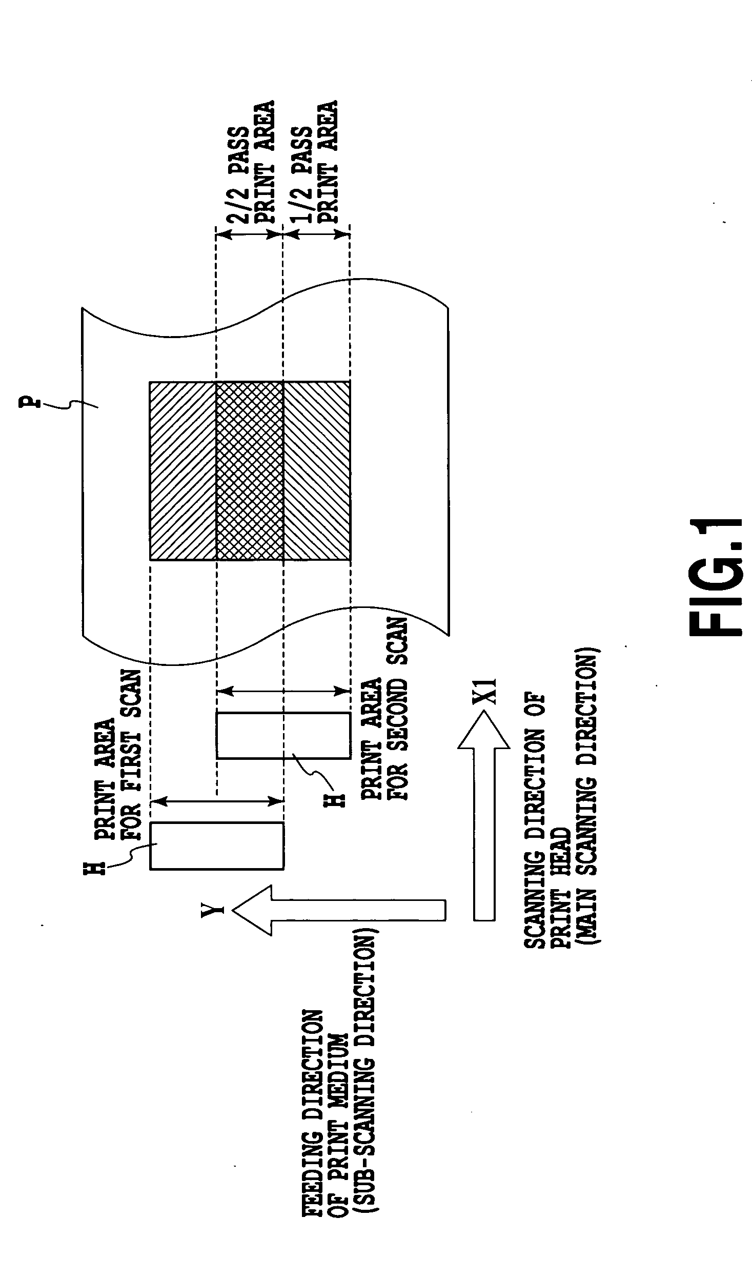
[0120] In FIG. 15, an image or the like is printed in a print area for the first scan by causing the print head H to eject the ink on the basis of print data while moving the print head H in the main scanning direction (the direction of the arrow X1). The present embodiment performs control such that after printing by a forward scan, the print medium is not fed before a bac...

embodiment 3

[0126] In the present embodiment, the time difference unevenness is suppressed by selecting the scan speed of the print head, that is, the movement speed of the carriage during printing, depending on the width of the print medium.

[0127]FIG. 19 is a diagram showing the evaluation of images for the relationship between the width of the print medium and the occurrence of time difference unevenness observed if the movement speed of the carriage is changed. A five-ranking sensory evaluation similar to that used in FIG. 14 is used as an evaluating method. Evaluation is made for two cases of 25 inch / sec and 50 inch / sec. As is apparent from FIG. 19, with any print medium width, the print time difference decreases at the higher carriage speed, that is, 50 inch / sec. As a result, the time difference unevenness can be suppressed.

[0128] In the print control according to the present embodiment, in the step S503 of the process in FIG. 10, shown in connection with the first embodiment, the width ...


PUM


Abstract

There is provided an ink jet printing apparatus that suppresses density unevenness caused by a difference in print time resulting from printing based on a bidirectional multi-pass printing system. With a relatively small print medium width, the time difference unevenness does not occur even in 2 pass printing. Accordingly, the 2 pass printing is selected. With a relatively large print medium width, selection of the 2 pass printing may make the density unevenness significant. Accordingly, the density unevenness is suppressed by selecting 8 pass printing. That is, in the 8 pass printing, the same area is scanned eight times, which is four times as frequent as the twice in the 2 pass printing. This reduces the size of each area having different densities, while increasing a cycle frequency at which a high and low densities are alternately repeated. As a result, the time difference unevenness is not perceived easily.

Description

BACKGROUND OF THE INVENTION [0001] 1. Field of the Invention [0002] The present invention relates to an ink jet printing apparatus and an ink jet printing method, and more specifically, to a configuration that resolves an uneven density attributed to the difference in print time between passes which may occur during printing based on what is called a multi-pass printing system. [0003] 2. Description of the Related Art [0004] As a printing apparatus in a printer, a copy machine, a facsimile machine, or the like or a printing apparatus used as equipment for outputting information processed by composite electronic equipment or a workstation including a computer, a word processor, or the like, an ink jet system-based printing apparatus is popular which can use a relatively simple configuration to print various print medium such as paper, cloths, plastic sheets, and OHP sheets. This system is basically of a non-contact printing type and does not depend on the type of print medium. Accord...

Claims


Application Information

Patent Timeline
Patent Type & Authority Applications(United States)
IPC IPC(8): B41J2/21B41J11/00B41J19/14B41J2/01
CPCB41J2/2132B41J19/142B41J11/0025B41J11/002B41J11/00244B41J11/0022
Inventor HARA, KATSUSHI
Owner CANON KK
Why Eureka
Try Eureka