
Inkjet recording head and inkjet recording apparatus

a recording head and inkjet technology, applied in printing and other directions, can solve the problems of inability to eject ink from the nozzle, clogging of the nozzle, and inability to effectively remove ink, etc., and achieve the effect of effective removal, short expulsion time, and greater impa

Inactive Publication Date: 2008-07-08
FUJIFILM CORP
View PDF7 Cites 4 Cited by
  • Summary
  • Abstract
  • Description
  • Claims
  • Application Information

AI Technical Summary

Benefits of technology

[0020]The present invention has been contrived in view of such circumstances, and an object thereof is to provide an inkjet recording head and an inkjet recording apparatus wherein thickened portions of ink in the head can be removed, air bubbles can be effectively expelled, regular ejection can be restored in a short time with a small amount of ink, and the restoring operation can be performed in near real time.
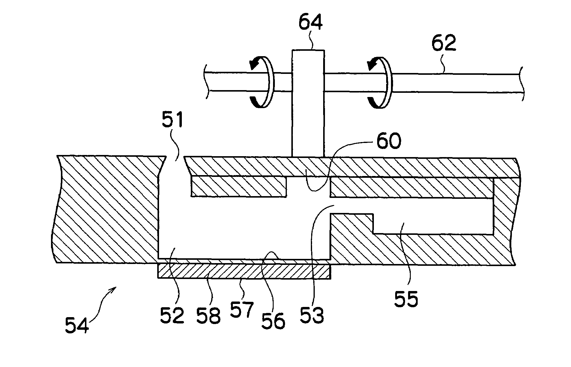
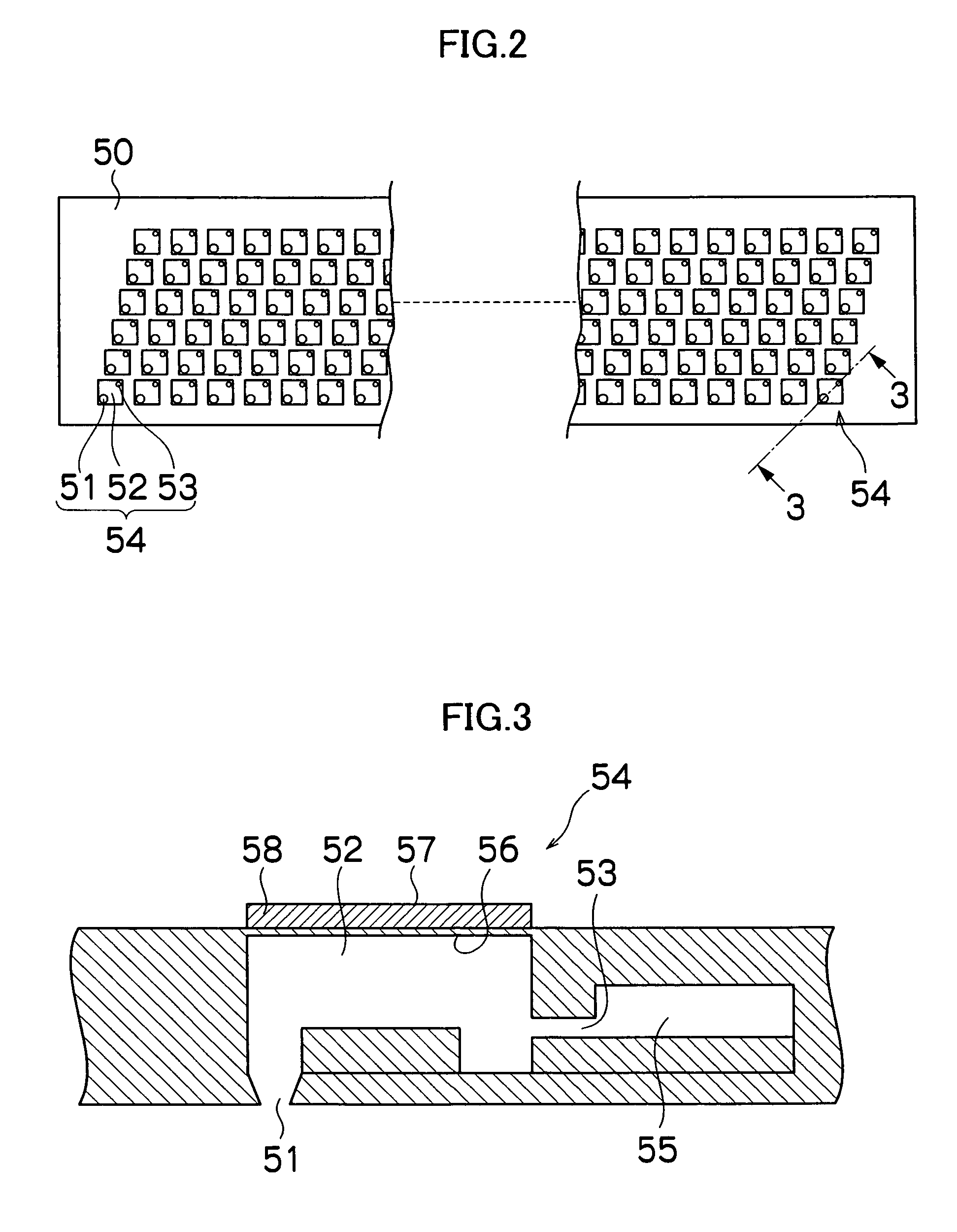
[0022]Thus, since a second vibrating plate for inducing ejection for maintenance separately from regular ejection and a second actuator for deforming the second vibrating plate are provided, thickened ink and ink with air bubbles mixed in can be reliably removed, and the second vibrating plate is configured so as to be deformed by a greater pressure than the first vibrating plate for regular ejection (by having greater rigidity, for example), whereby purging can be performed with greater impact during maintenance than during regular ejection without affecting regular ejection, and a more reliable restoring operation is made possible.
[0023]When a plurality of pressure chambers are provided to the inkjet recording head, a plurality of second actuators which deform a plurality of second vibrating plates provided to the plurality of pressure chambers are driven by a single actuator drive source. The configuration of the apparatus can thereby be simplified, and costs can be reduced.
[0025]Preferably, the second vibrating plate is disposed near the ink supply port. Thus, air bubbles, impurities, and the like in the pressure chamber between the supply port and the ejection port (nozzle) can be expelled all at once from the nozzle side, and the degree of freedom with the configuration of the apparatus can be increased due to the separate structure of the second actuator for deforming the second vibrating plate.
[0027]According to the inkjet recording head and inkjet recording apparatus relating to the present invention, thickened portions can be effectively removed and air bubbles expelled in a short time with a small amount of ink by applying a greater impact than can be produced during regular ejection in the pressure chamber, and the restoring operation can be reliably performed by returning to regular ejection.

Problems solved by technology

However, since the ink in the nozzle is exposed to air during printing, the ink dries in a nozzle that does not undergo ejection for a long period of time, and it is possible that the viscosity of the ink will increase, the nozzle will be clogged, and the nozzle will run out of ink, making ejection impossible.
Also, ink cannot be ejected from the nozzle if air bubbles mixed in the ink supply channel accumulate in the ink ejection head or in front of the filter for removing impurities disposed in the ink supply channel and the supply of ink is blocked by these accumulated air bubbles.
However, the methods proposed in conventional practice have had problems in that air bubbles, impurities, thickened ink, or the like in a channel reaching from an individual flow channels to a nozzle via a pressure chamber are removed by negative or positive pressure from a location separate from any pressure chamber (ink chamber), a long flow channel extends from the pressure source to the point of application, and due to the inertia of the ink therein, an impact force cannot be applied to the location of the problem, a great number of trials are needed until the air bubbles, impurities, thickened ink, or the like are effectively removed, and the ink develops defects.
Also, the example disclosed in Japanese Patent Application Publication No. 2000-177126 has problems in that air bubbles and the like are expelled by inducing the maximum possible vibration using an ejection actuator, but the effects are limited and it is unlikely that the clogging will be sufficiently dispersed because the ejection actuator is optimized for the original ejection and an extra force cannot be produced.
Also, the example disclosed in Japanese Patent Application Publication No. 2003-145782 has problems in that costs increase in the case of a head having multiple nozzles when an ultrasonic element is to be installed in each individual nozzle.
Furthermore, the examples disclosed in Japanese Patent Application Publication Nos. 9-150509 and 9-193379 have problems in that they are designed to clean the ink chamber but are not designed to resume printing by immediately dispersing clogs when the nozzle is clogged during printing, and the restoring operation cannot be performed in real time.

Method used


Image

  • Inkjet recording head and inkjet recording apparatus
  • Inkjet recording head and inkjet recording apparatus
  • Inkjet recording head and inkjet recording apparatus

Examples


Embodiment Construction

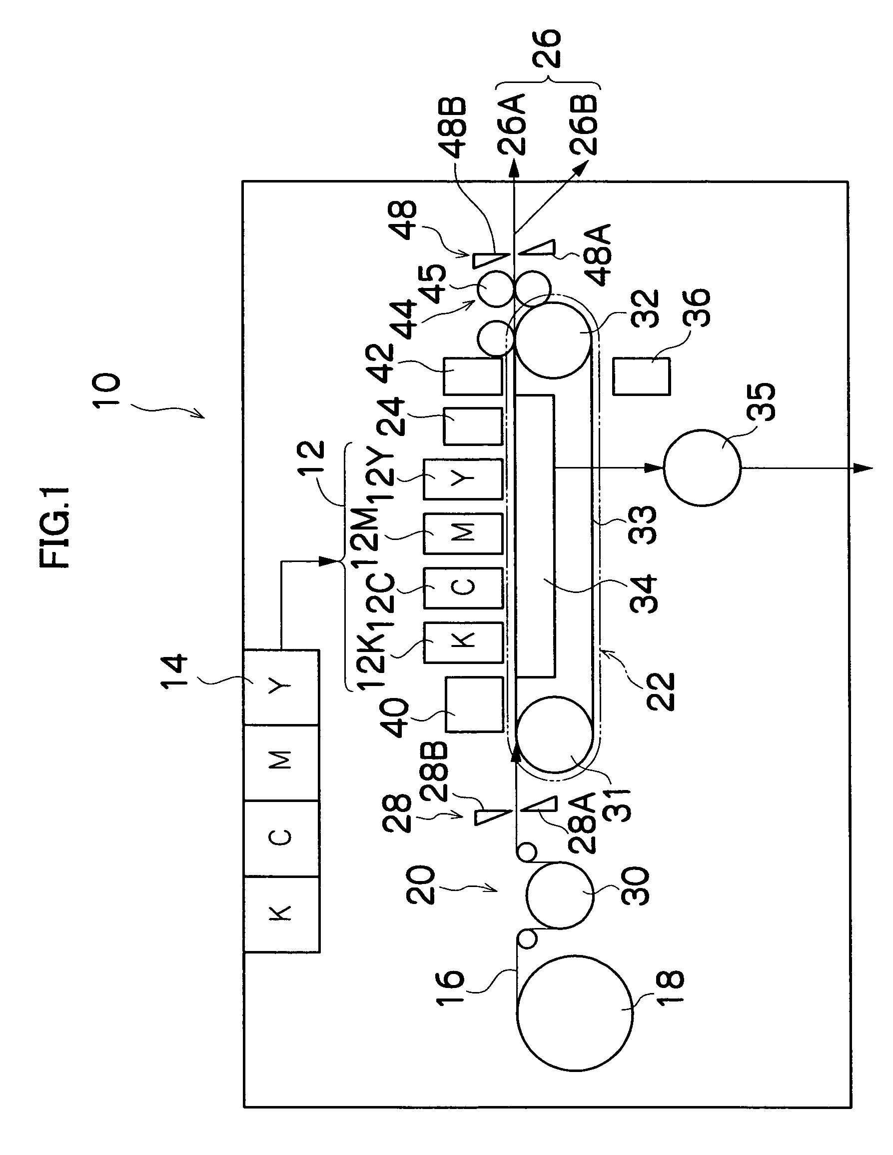
[0038]FIG. 1 is a general schematic drawing of an inkjet recording apparatus according to an embodiment of the present invention. As shown in FIG. 1, the inkjet recording apparatus 10 comprises: a printing unit 12 having a plurality of print heads 12K, 12C, 12M, and 12Y for ink colors of black (K), cyan (C), magenta (M), and yellow (Y), respectively; an ink storing / loading unit 14 for storing inks to be supplied to the print heads 12K, 12C, 12M, and 12Y; a paper supply unit 18 for supplying recording paper 16; a decurling unit 20 for removing curl in the recording paper 16; a suction belt conveyance unit 22 disposed facing the nozzle face (ink-droplet ejection face) of the print unit 12, for conveying the recording paper 16 while keeping the recording paper 16 flat; a print determination unit 24 for reading the printed result produced by the printing unit 12; and a paper output unit 26 for outputting image-printed recording paper (printed matter) to the exterior.

[0039]In FIG. 1, a s...


PUM


Abstract

The inkjet recording head comprises: a first vibrating plate which forms part of a pressure chamber connecting an ink supply port and an ink ejection port; a first actuator which induces ink ejection from the ink ejection port for printing by deforming the first vibrating plate; a second vibrating plate which forms part of the pressure chamber; and a second actuator which induces ink ejection from the ink ejection port for performing maintenance by deforming the second vibrating plate, wherein a relationship K1>K2 is established between a ratio K1 of a volume of ink expelled by deformation of the first vibrating plate in relation to a pressure applied to the first vibrating plate by the first actuator during the ink ejection for printing, and a ratio K2 of a volume of ink expelled by deformation of the second vibrating plate in relation to a pressure applied to the second vibrating plate by the second actuator during the ink ejection for maintenance.

Description

BACKGROUND OF THE INVENTION[0001]1. Field of the Invention[0002]The present invention relates to an inkjet recording head and an inkjet recording apparatus, and more particularly to an inkjet recording head and an inkjet recording apparatus wherein maintenance can be performed by reliably removing ink that has thickened due to drying, ink with air bubbles mixed in, or other such ink that causes nozzle clogging or ejection problems from the nozzle.[0003]2. Description of the Related Art[0004]Conventionally, one known example of an image recording apparatus is an inkjet recording apparatus (inkjet printer) that has an inkjet head (ink discharge head) with an alignment of multiple nozzles, and that forms an image on a recording medium by discharging ink from the nozzles while moving the inkjet recording head and the recording medium relatively to each other.[0005]Various methods for discharging ink in inkjet printers are conventionally known. One known example is a piezoelectric system...

Claims


Application Information

Patent Timeline
Patent Type & Authority Patents(United States)
IPC IPC(8): B41J2/045B41J2/165
CPCB41J2/16517
Inventor SANADA, KAZUO
Owner FUJIFILM CORP
Learn More