Centrifugal separator for cleaning gases

a centrifugal separator and cleaning gas technology, applied in centrifuges, separation processes, dispersed particle separation, etc., can solve the problems of reducing the risk of liquid which has been separated out evaporating or being reincorporated, and achieve the effect of efficient cleaning of gas flows

Active Publication Date: 2008-07-08
GRIMALDI DEV AB
View PDF7 Cites 64 Cited by
  • Summary
  • Abstract
  • Description
  • Claims
  • Application Information

AI Technical Summary

Benefits of technology

[0004]An object of the present invention is to produce a separating device which has the ability to efficiently clean gas flows which contain relatively large quantities of liquid and / or solid particles (>approx. 10 g / m3).
[0005]To this end, the device according to the invention which was mentioned at the outset is characterized in that a number of parallel guide rails, which run helically, are arranged on the inner side of the housing and extend axially at least over a major part of the length of the rotor and in that the outlet, in the housing, for cleaned gas is located, with respect to the axis, at one end of the rotor while the outlet for the particles which have been collected on the housing wall is located at the opposite axial end of the rotor, with the guide rails being arranged in a direction on the inner side of the housing in relation to the direction of rotation of the rotor which is such that a peripherally outer part of a gas vortex generated by the rotor is forced to entrain the particles which have been collected between the guide rails toward the particle outlet. In this way, the layer of the gas stream which is located closest to the housing wall can be caused, with the aid of the guide rails, to travel in the axial direction which is opposite to that of the main flow of the gas and, in this connection, entrain the liquid, which has been collected on the housing wall, in an opposite direction to that of the main stream of cleaned gas, to a liquid outlet where the liquid can be fed out in a quiet region where there is no risk of disturbances from a powerful gas flow. The guide rails also dampen the rotation of the gas closest to the housing wall, with this in turn decreasing the risk of liquid which has been separated out evaporating or being reincorporated.

Problems solved by technology

However, when such a separator is used for separating a large content of liquid and / or particles from gases, problems can arise due to the fact that the liquid flow can penetrate through the air cushion vortex and reach the screening element either directly or as splashes from slits or apertures at the liquid outlet, with it being possible for some of the liquid to be entrained out toward the outlet for the cleaned gas stream and to be reincorporated into the latter.
The guide rails also dampen the rotation of the gas closest to the housing wall, with this in turn decreasing the risk of liquid which has been separated out evaporating or being reincorporated.

Method used


Image

  • Centrifugal separator for cleaning gases
  • Centrifugal separator for cleaning gases

Examples


Embodiment Construction

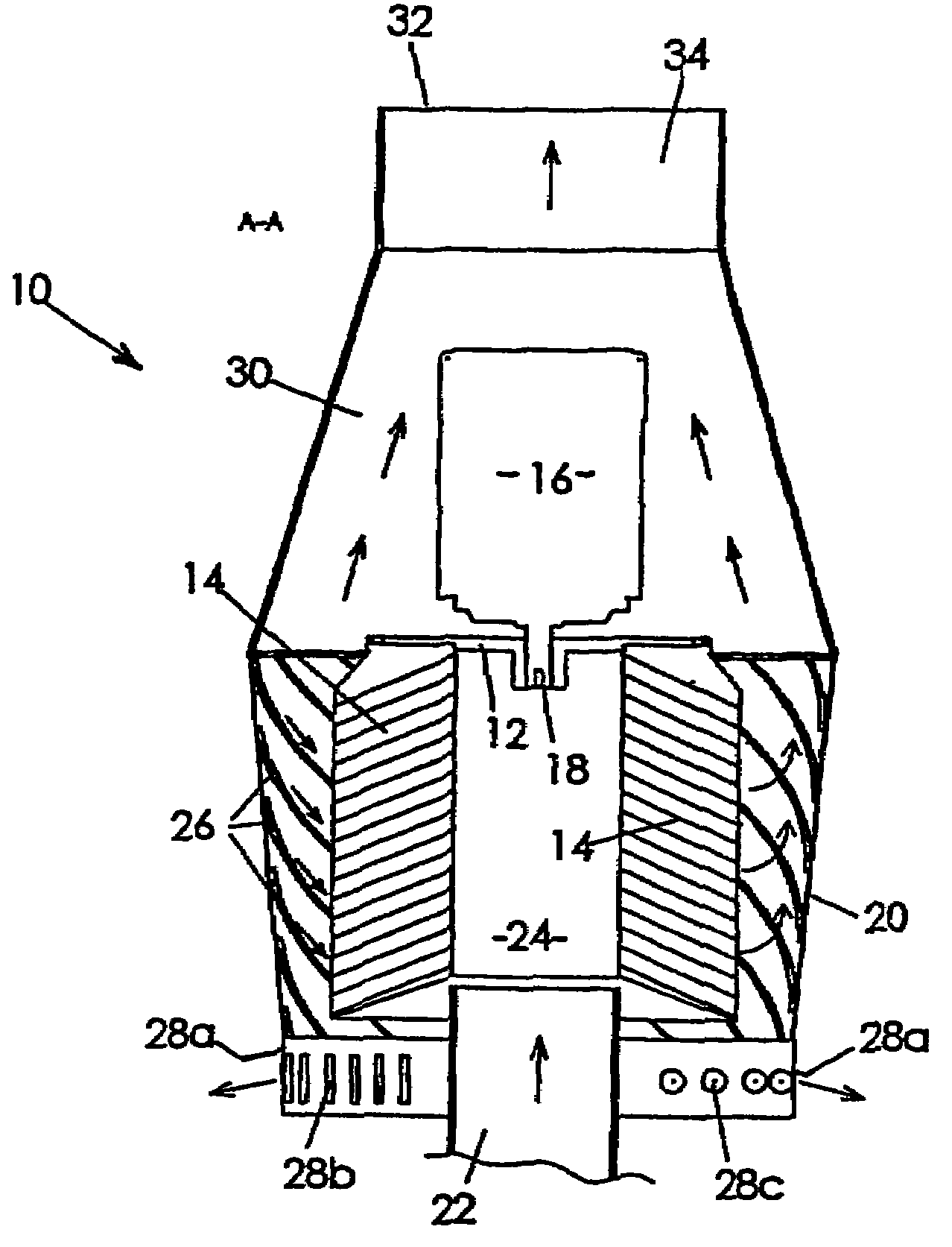
[0009]In FIG. 1, 10 denotes, in a general manner, a centrifugal separator according to the invention for separating solid and / or liquid particles which are suspended in gas media, for example for cleaning air which contains an oil mist or other very fine particles. In order to meet increasing environmental demands within industrial premises, it is frequently necessary to conduct out polluted air, or other gases, by way of long conduit systems, to large external cleaning devices.

[0010]The centrifugal separator 10 according to the invention is so compact that it can be placed directly on the machine which is generating a contaminated gas medium and makes it possible to clean such contaminated air so efficiently that the latter can be released into the premises in direct association with the process machine or machines in question.

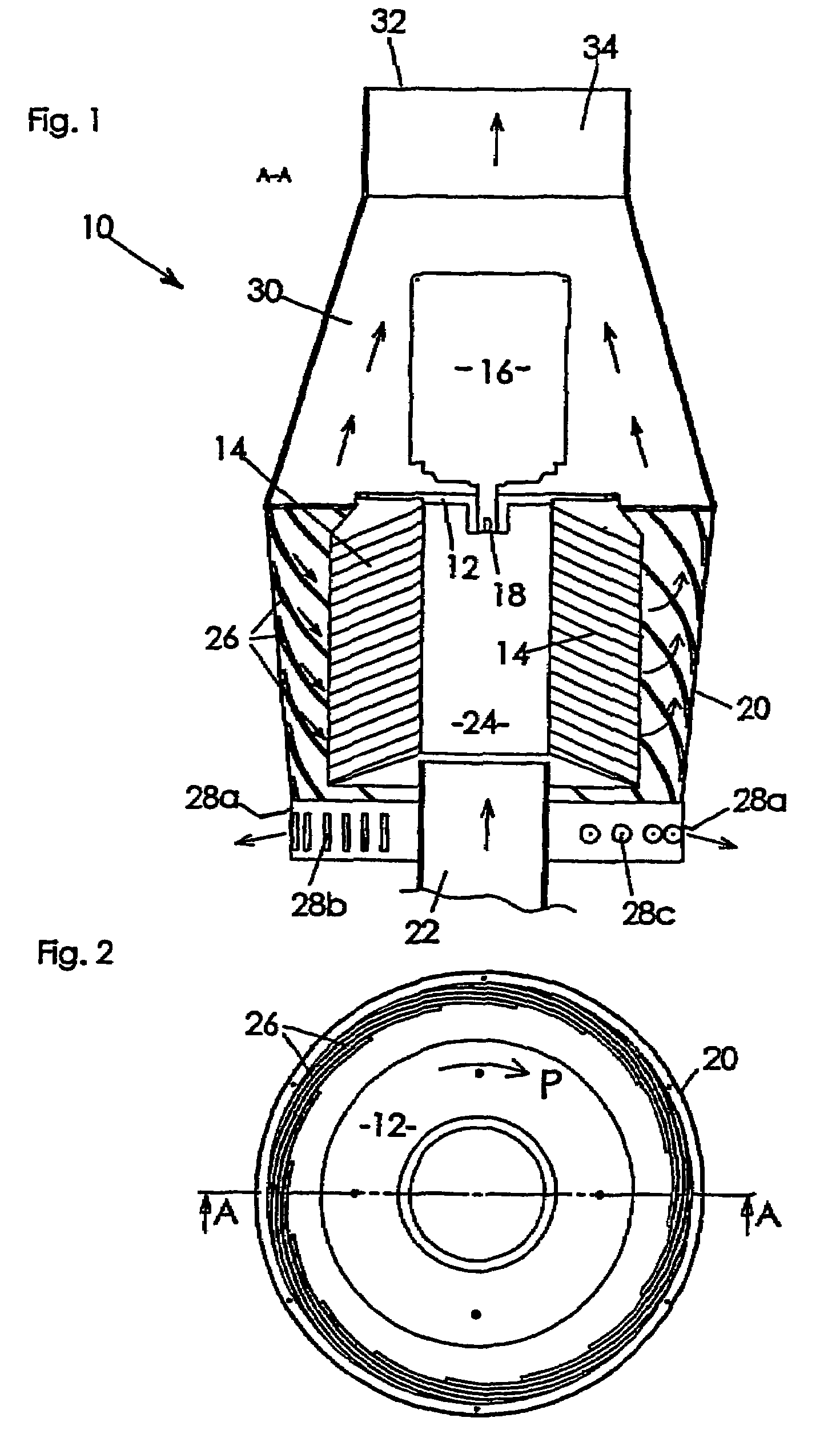
[0011]The centrifugal separator 10 comprises a rotor 12 which has a number of sedimentation members in the form of inset plates 14 which are mounted on it an...


PUM

PropertyMeasurementUnit
lengthaaaaaaaaaa
of rotationaaaaaaaaaa
distanceaaaaaaaaaa

Abstract

A centrifugal separator device (10) for separating solid and / or liquid particles which are suspended in gas media, which device comprises a rotor (12) which is provided sedimentation members (14), which is rotatably mounted in a surrounding stationary housing (20) and which has a central inlet for the gas medium which is to be cleaned. The housing (20) has, on the one hand, an outlet (32) for cleaned gas which, during its passage through the sedimentation members (14) in the rotor (12), has been freed form solid and / or liquid particles, and, on the other hand, an outlet (28 a-c) for solid and / or liquid particles which have been transferred onto the inner side of the housing. A number of parallel guide rails (26), which run helically, are arranged on the inner side of the housing and extends axially at least over a major part of the length of the rotor (12), and the outlet (32) in the housing for cleaning gas is located, with respect to the axis, at one end of the rotor (12) while the outlet (28a-c9 for the particles which have been collected on the housing wall is located at the opposite axial end of the rotor. The guide rails (26) are arranged in a direction on the inner side of the housing in relation to the direction of rotation of the rotor which is such that a peripherally outer of a gas vortex generated by the rotor is forced to entrain the particles which have been collected between the guide rails toward the particles outlet.

Description

TECHNICAL FIELD[0001]The present invention relates to a device for separating solid and / or liquid particles which are suspended in gas media, which device comprises a rotor which is provided with sedimentation members, which is rotatably mounted in a surrounding, stationary housing and which has a central inlet for the gas medium which is to be cleaned, with the housing having, on the one hand, an outlet for cleaned gas which, during its passage through the sedimentation members in the rotor has been freed from solid and / or liquid particles, and, on the other hand, an outlet for the solid and / or liquid particles, which are firstly deposited on the sedimentation members and, after that transferred, by means of a centrifugal force, onto a side wall of the housing, with the outlet for the solid and / or liquid particles having the form of at least one aperture which is included in the side wall of the housing.BACKGROUND TO THE INVENTION[0002]SE-A-0202671-4 describes a centrifugal separat...

Claims


Application Information

Patent Timeline
Patent Type & Authority Patents(United States)
IPC IPC(8): B01D45/00B04B5/12B04B7/02
CPCB04B5/12B04B7/02B04B2005/125
Inventor LAGERSTEDT, TORGNYINGE, CLAESFRANZEN, PETERMAEHANS, OLEVSANDGREN, MARTIN
Owner GRIMALDI DEV AB
Why Eureka
Try Eureka