Fluorescent microscope
a fluorescent microscope and microscope technology, applied in the field of fluorescence microscopes, can solve the problems of insufficient observation light amount and inability to be easily handled, and achieve the effect of reducing specimen fading and saving power
- Summary
- Abstract
- Description
- Claims
- Application Information
AI Technical Summary
Benefits of technology
Problems solved by technology
Method used
Image
Examples
first embodiment
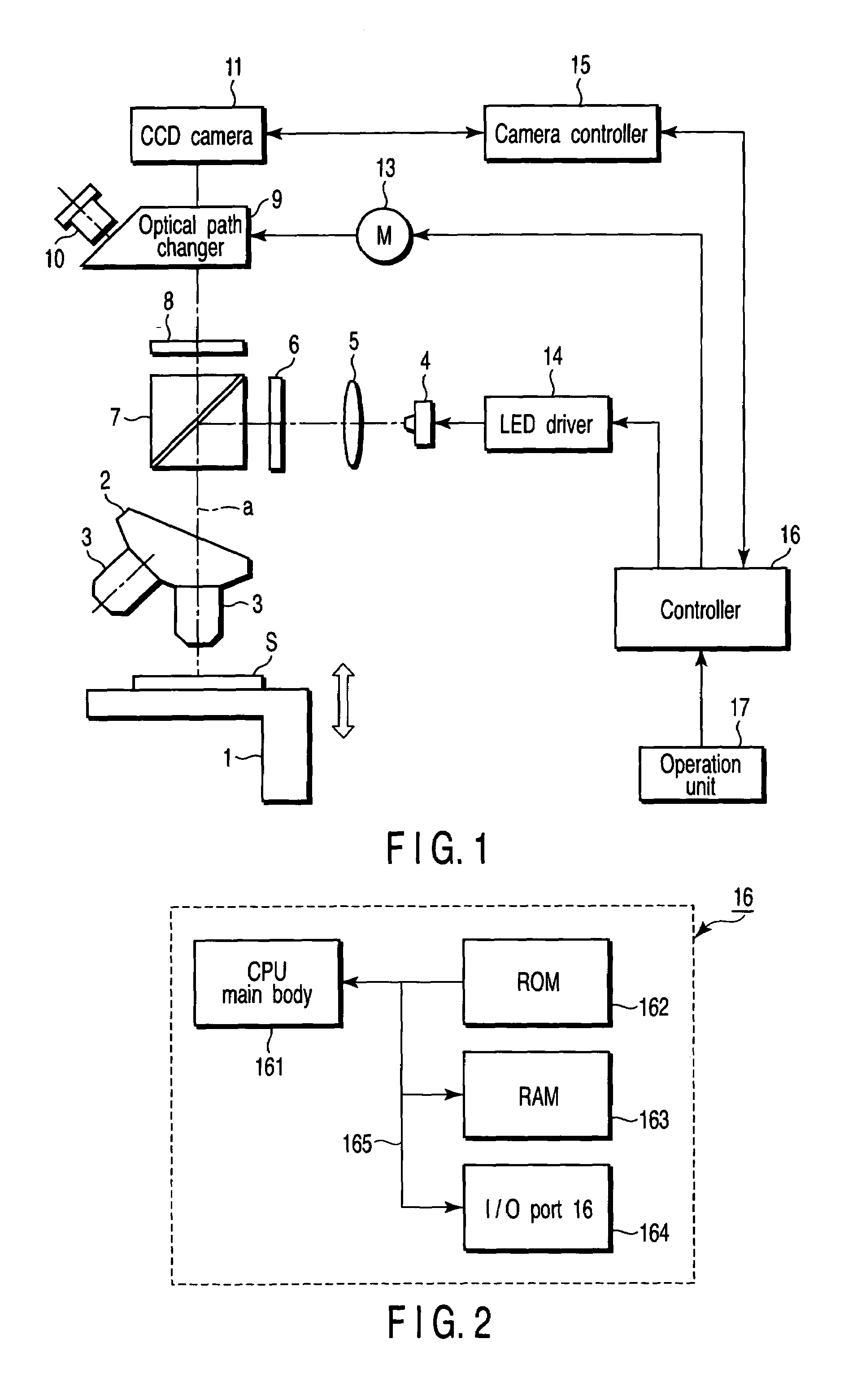
[0024]FIG. 1 is a diagram showing a schematic configuration of a fluorescent microscope according to a first embodiment of the present invention.
[0025]In FIG. 1, a specimen S is mounted on a stage 1. The stage 1 is capable of vertical movement in an optical axis direction (arrow direction indicated in the drawing) so that the specimen S can be focused on.
[0026]An objective lens 3 is disposed above the stage 1 in proximity to the specimen S. A plurality of objective lenses 3 (only two of them are shown in the drawing) with different magnifications is held to a revolver 2, and the desired objective lens 3 is selectively positioned on an observation optical path a by the operation of the revolver 2.
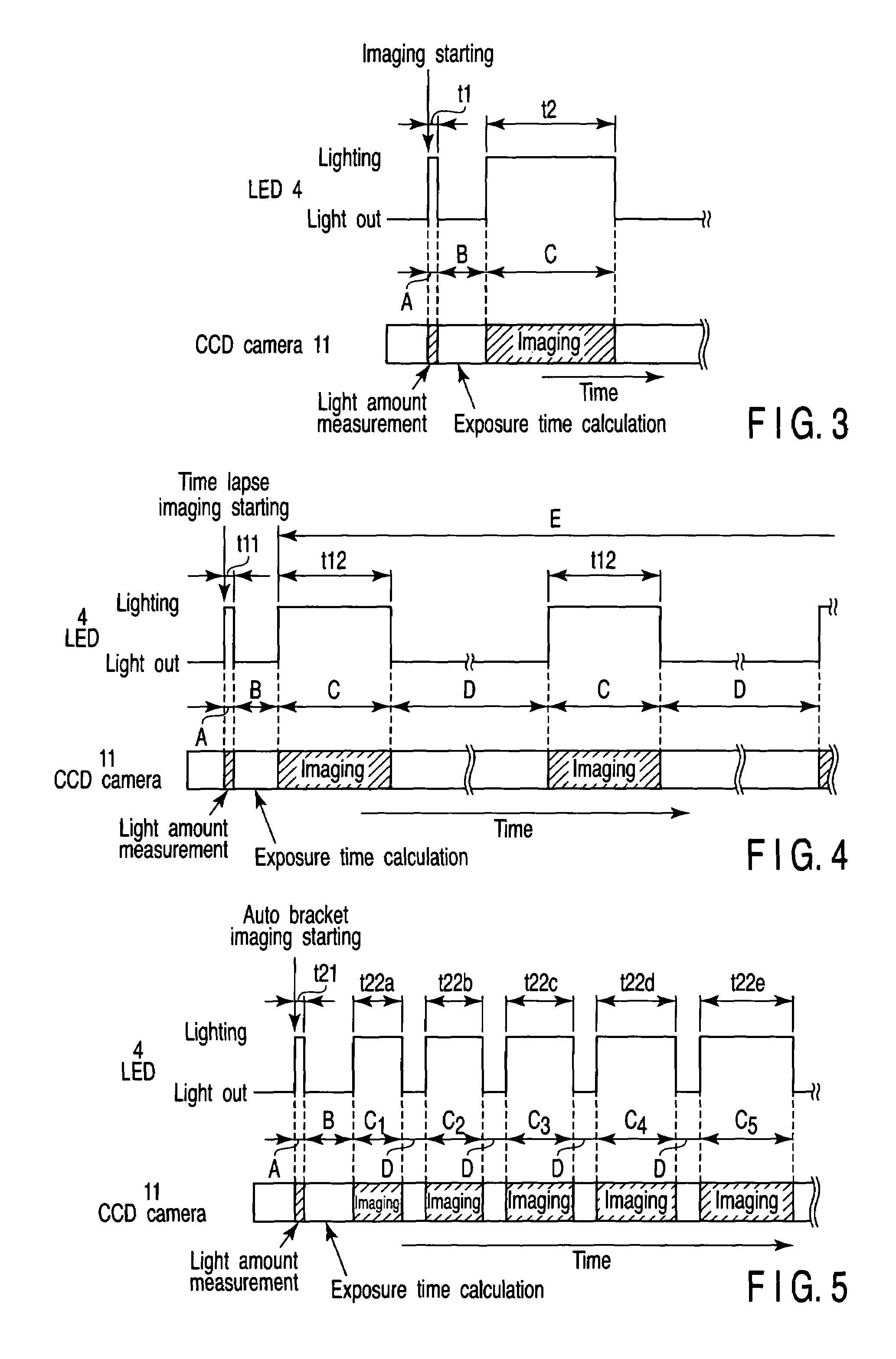
[0027]A collector lens 5 and an excitation filter 6 that configure an illumination optical system are disposed on an optical path of light emitted from an LED 4 as a small light emitting element which is an illumination light source. The collector lens 5 converts the light from the LED 4 int...
second embodiment
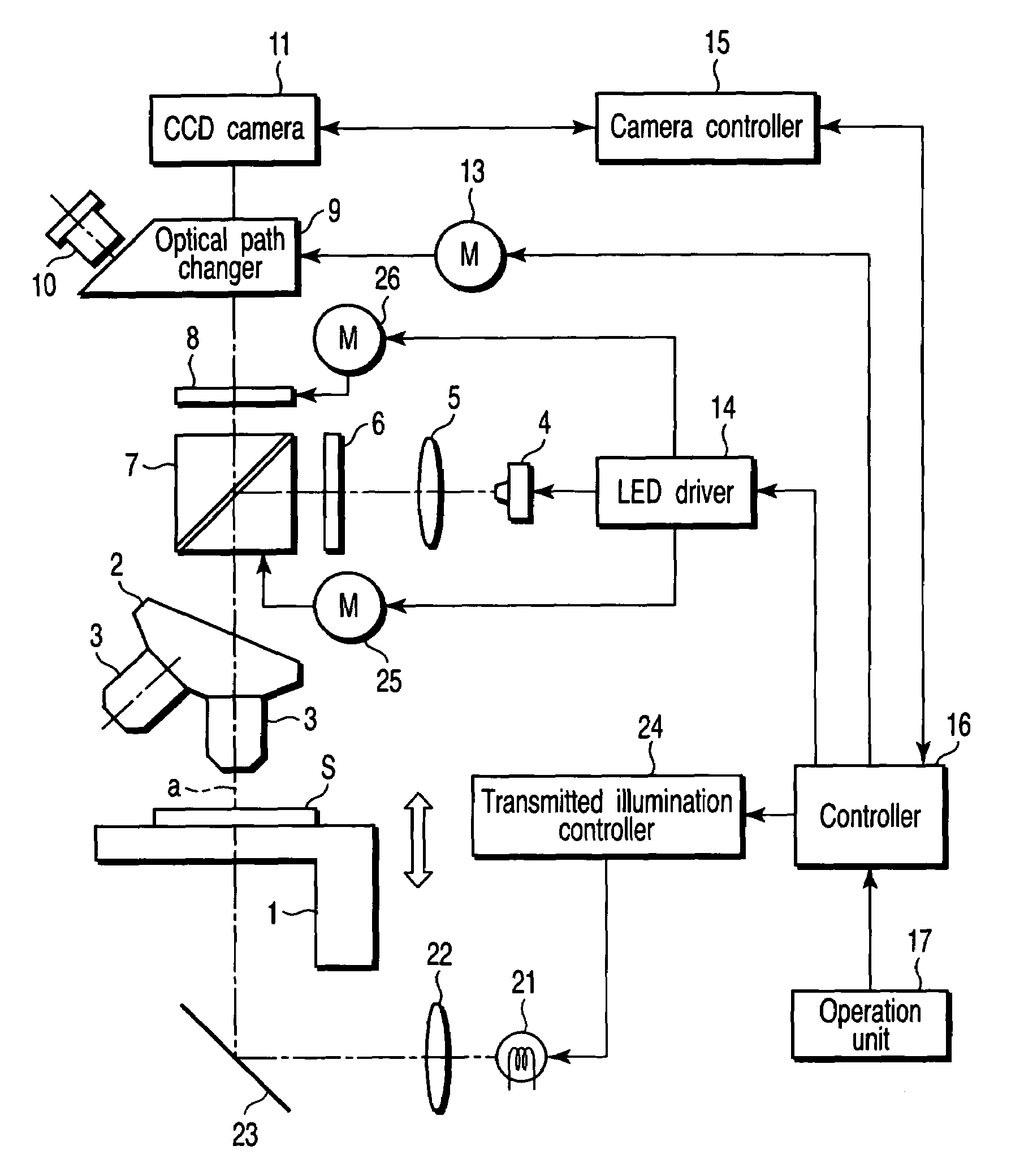
[0064]A second embodiment of the present invention will be described referring to FIG. 6.
[0065]FIG. 6 is a diagram showing a schematic configuration of the fluorescent microscope according to a second embodiment of the present invention, in which the same signs are given to the same parts as those in FIG. 1.
[0066]The second embodiment is different from the first embodiment in that a transmitted illumination system as illumination means is added in addition to the LED 4 used for the fluorescence observation. In FIG. 6, a mercury lamp, a halogen lamp or the like is used for a transmitted illumination light source 21 as a second light source.
[0067]A transmitted illumination collector lens 22 and a reflection mirror 23 are disposed on an optical path of light emitted from the transmitted illumination light source 21. The transmitted illumination collector lens 22 converts the light from the transmitted illumination light source 21 into parallel light. The reflection mirror 23 reflects t...
third embodiment
[0074]A third embodiment of the present invention will next be described.
[0075]The third embodiment is concerned with turn off timing of the LED 4 which performs the excitation light illumination. The LED 4 turns off at the moment of photography by the CCD camera 11 in the first and second embodiments, but the third embodiment is applied to the case where the observer performs the fluorescence observation with the naked eye via the eyepiece 10. If the excitation light illuminated during observation is blocked each time the observer is not looking through the eyepiece 10, that is, each time the observation is discontinued, fading of the specimen can be reduced. However, in effect, when the observation is frequently continued / discontinued repetitively, it requires time and labor if a turn off switch on the operation unit 17 is operated to turn off the LED 4 each time, and therefore, the excitation light is often illuminated continuously. Moreover, the observer might forget to block th...
PUM
 Abstract
Description
Claims
Application Information
 - R&D
- Intellectual Property
- Life Sciences
- Materials
- Tech Scout
- Unparalleled Data Quality
- Higher Quality Content
- 60% Fewer Hallucinations
Browse by: Latest US Patents, China's latest patents, Technical Efficacy Thesaurus, Application Domain, Technology Topic, Popular Technical Reports.
© 2025 PatSnap. All rights reserved.Legal|Privacy policy|Modern Slavery Act Transparency Statement|Sitemap|About US| Contact US: help@patsnap.com


