Structure of optic film

a technology of optic film and structure, applied in the field of optic film, can solve problems such as form interference patterns

Inactive Publication Date: 2008-07-08
GAMMA OPTICAL +1
View PDF8 Cites 21 Cited by
  • Summary
  • Abstract
  • Description
  • Claims
  • Application Information

AI Technical Summary

Problems solved by technology

Thus, when the regular straight beam passes through gaps between units of thin-film transistors and the color filters, diffraction of light occurs, which forms interference patterns in the liquid crystal display panel.
This often causes problems between the backlight module suppliers and the manufacturers of liquid crystal display panels, and is a trouble of pressing need to be overcome.

Method used


Image

  • Structure of optic film
  • Structure of optic film
  • Structure of optic film

Examples


Embodiment Construction

[0045]The following descriptions are of exemplary embodiments only, and are not intended to limit the scope, applicability or configuration of the invention in any way. Rather, the following description provides a convenient illustration for implementing exemplary embodiments of the invention. Various changes to the described embodiments may be made in the function and arrangement of the elements described without departing from the scope of the invention as set forth in the appended claims.

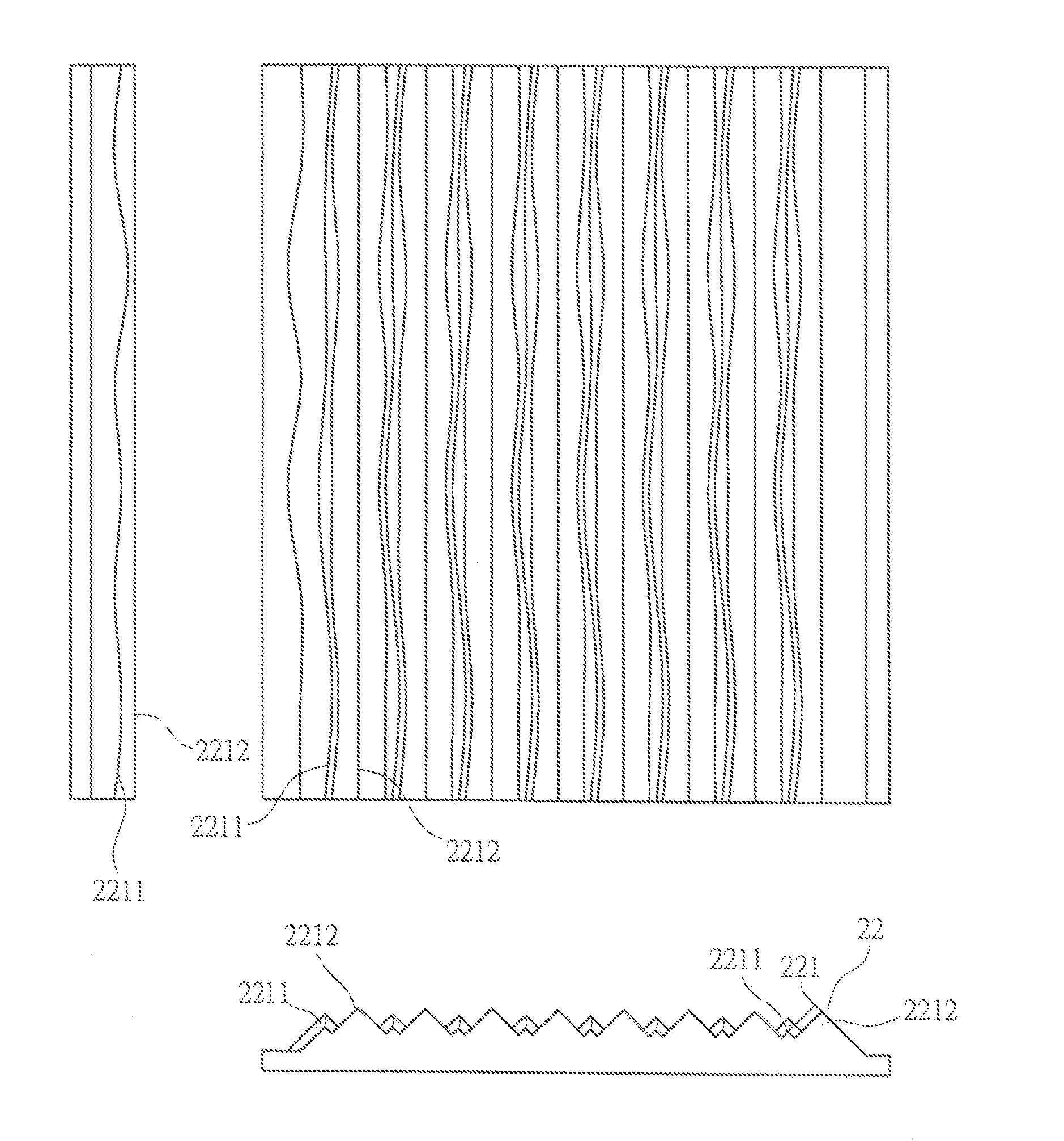
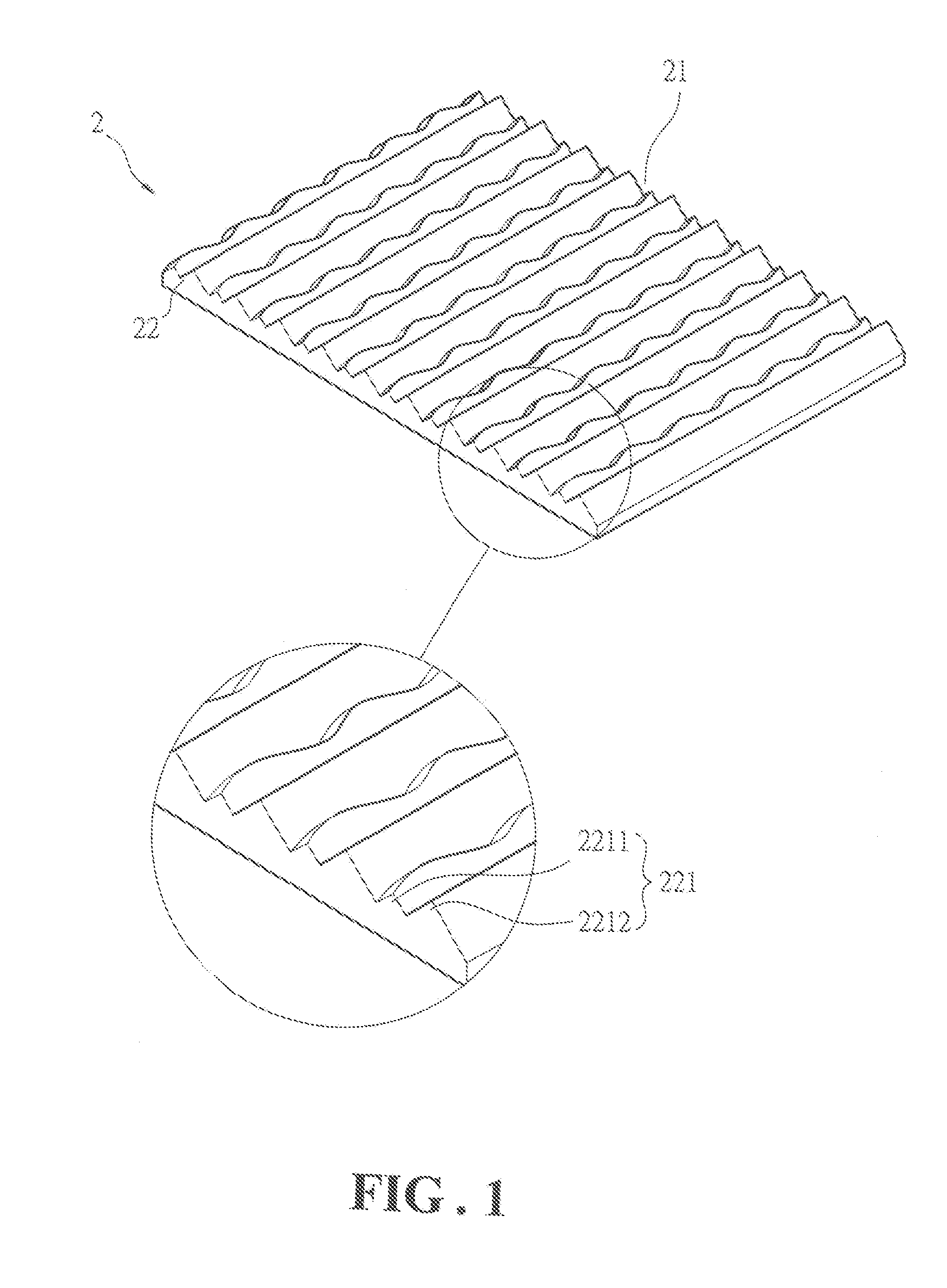
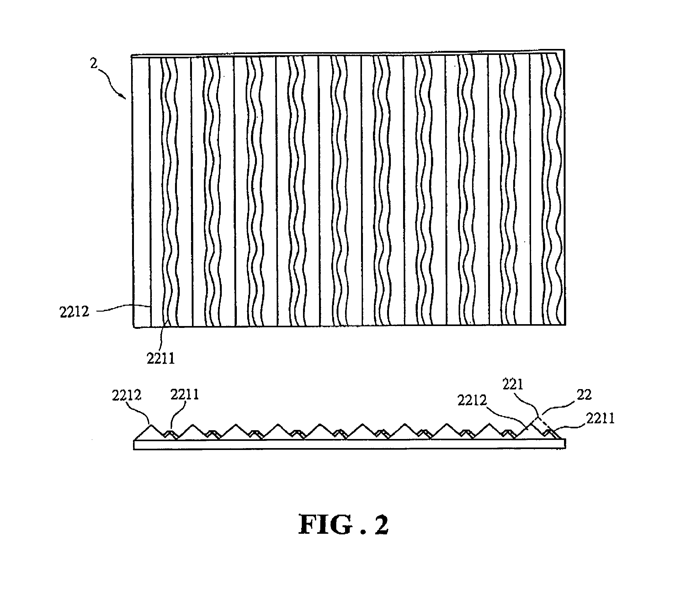
[0046]With reference to the drawings and in particular to FIG. 1, an optic film constructed in accordance with the present invention, generally designated with reference numeral 2, is made of material that has excellent light transmittance. The optic film 2 has a surface 21 on which a plurality of light guides 22 in the form of micro ribs is formed. The ribs of the light guides 22 can be made of the same material as a body of the optic film 2, or alternatively, the light guides 22 are made of mat...


PUM


Abstract

An optic film has a surface on which a plurality of rib-like micro light guides is formed. Each light guide includes a plurality of ridges, which are of different height and shows variation of height. Either a high ridge or a low ridge of the light guide is made a continuous left-and-right wavy configuration and / or a continuous up-and-down height-variation configuration. Thus, light transmitting through the optic film and converged by the light guides leaves the optic film in a form that is not very regular so as to facilitate subsequent use of the light in for example a liquid crystal panel.

Description

BACKGROUND OF THE INVENTION[0001](a) Technical Field of the Invention[0002]The present invention relates to an optic film, and in particular to a structure of optic film that allows light transmitting therethrough to leave in an irregular manner to facilitate subsequent use of the light.[0003](b) Description of the Prior Art[0004]A conventional backlight module provides a light source wherein light transmits through prism ribs formed on an optic film and thus proceeds in a very regular straight beam. The conventional backlight module, although effectively converting a linear light source into a surface light source, makes light transmitting through the prism ribs formed on the film so that the light proceeds ahead in a regular straight beam. On the other hand, a liquid crystal display panel comprises thin-film transistors and color filters which are of minute matrix arranged in an opposing manner. Thus, when the regular straight beam passes through gaps between units of thin-film tr...

Claims


Application Information

Patent Timeline
Patent Type & Authority Patents(United States)
IPC IPC(8): G02B13/00
CPCG02B5/0221G02B5/0278G02B5/0257G02B5/0231G02B5/02G02F1/1335
Inventor MAI, CHIEN-CHIN
Owner GAMMA OPTICAL
Why Eureka
Try Eureka