
Multi-function general purpose transceiver

a transceiver and multi-functional technology, applied in the field of transceivers, can solve the problems of machine being disabled or otherwise in need of service for an undesirably long time, and it is relatively expensive to employ an individual

Inactive Publication Date: 2008-07-08
STATSIGNAL IPC
View PDF604 Cites 248 Cited by
  • Summary
  • Abstract
  • Description
  • Claims
  • Application Information

AI Technical Summary

Benefits of technology

[0022]FIG. 8 is a flowchart illustrating a more detailed operatio

Problems solved by technology

One way this type of information has been communicated in the past has been to dispatch personnel to periodically check on such machinery If problems were noted, then the dispatched personnel communicated this information to a central dispatch or service location One shortcoming with this approach, however, is that it is relatively expensive to employ an individual to make these periodic status checks Also, a machine may be disabled or otherwise in need of service for a undesirably lengthy period of time between service checks, before the service condition is noted and reported.

Method used


Image

  • Multi-function general purpose transceiver
  • Multi-function general purpose transceiver
  • Multi-function general purpose transceiver

Examples


Embodiment Construction

[0023]Having summarized various aspects of the present invention, reference will now be made in detail to the description of the invention as illustrated in the drawings. While the invention will be described in connection with these drawings, there is no intent to limit it to the embodiment or embodiments disclosed therein. On the contrary, the intent is to cover all alternatives, modifications and equivalents included within the spirit and scope of the invention as defined by the appended claims.

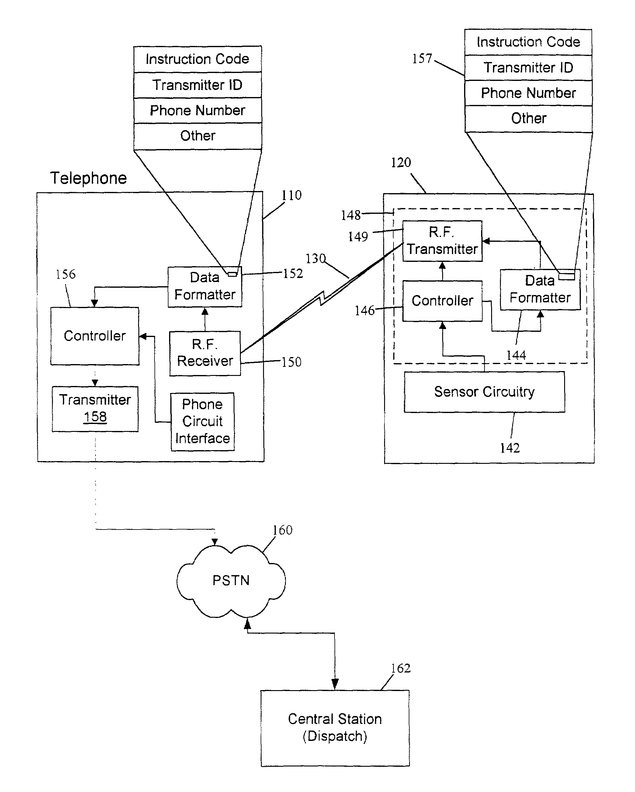
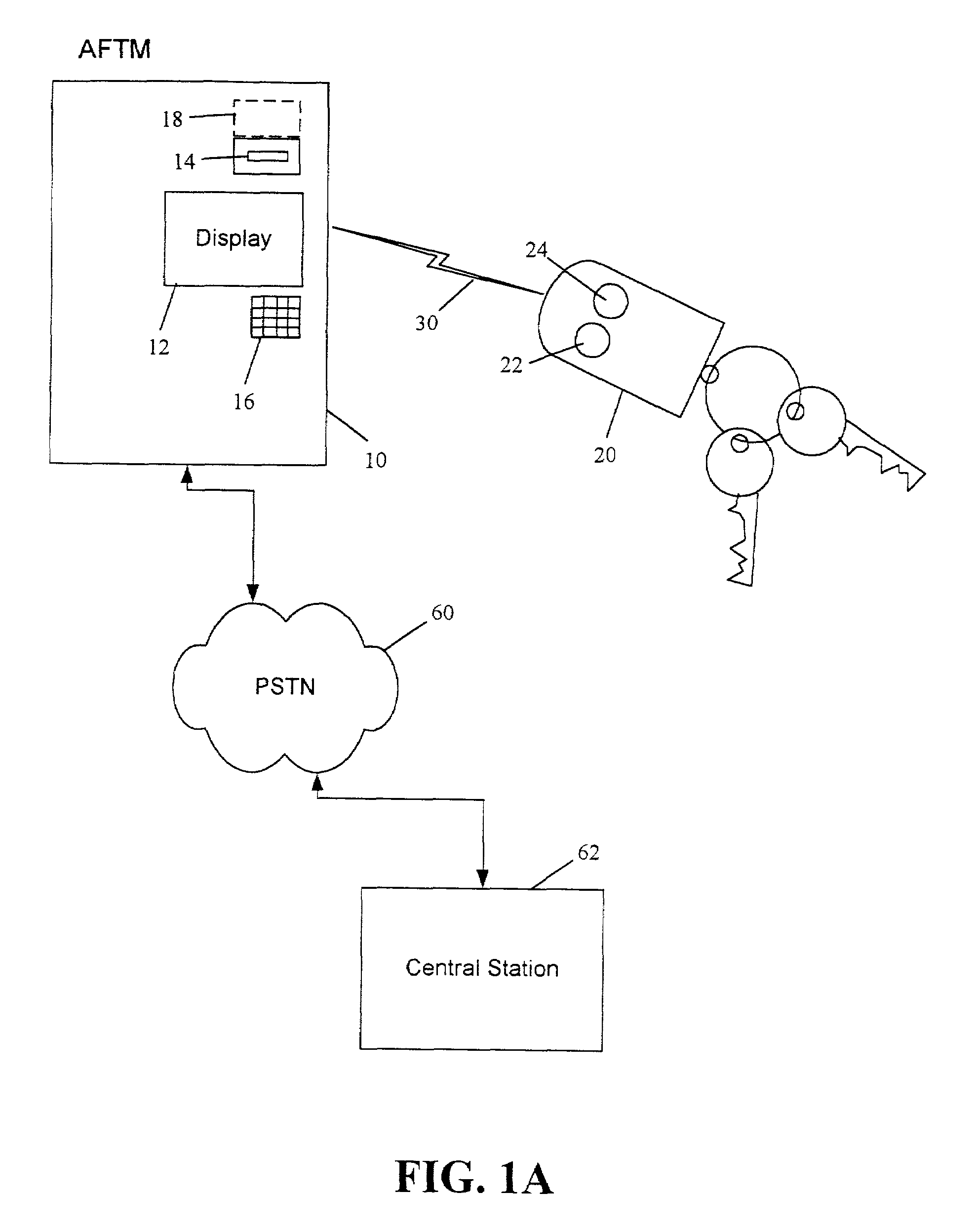
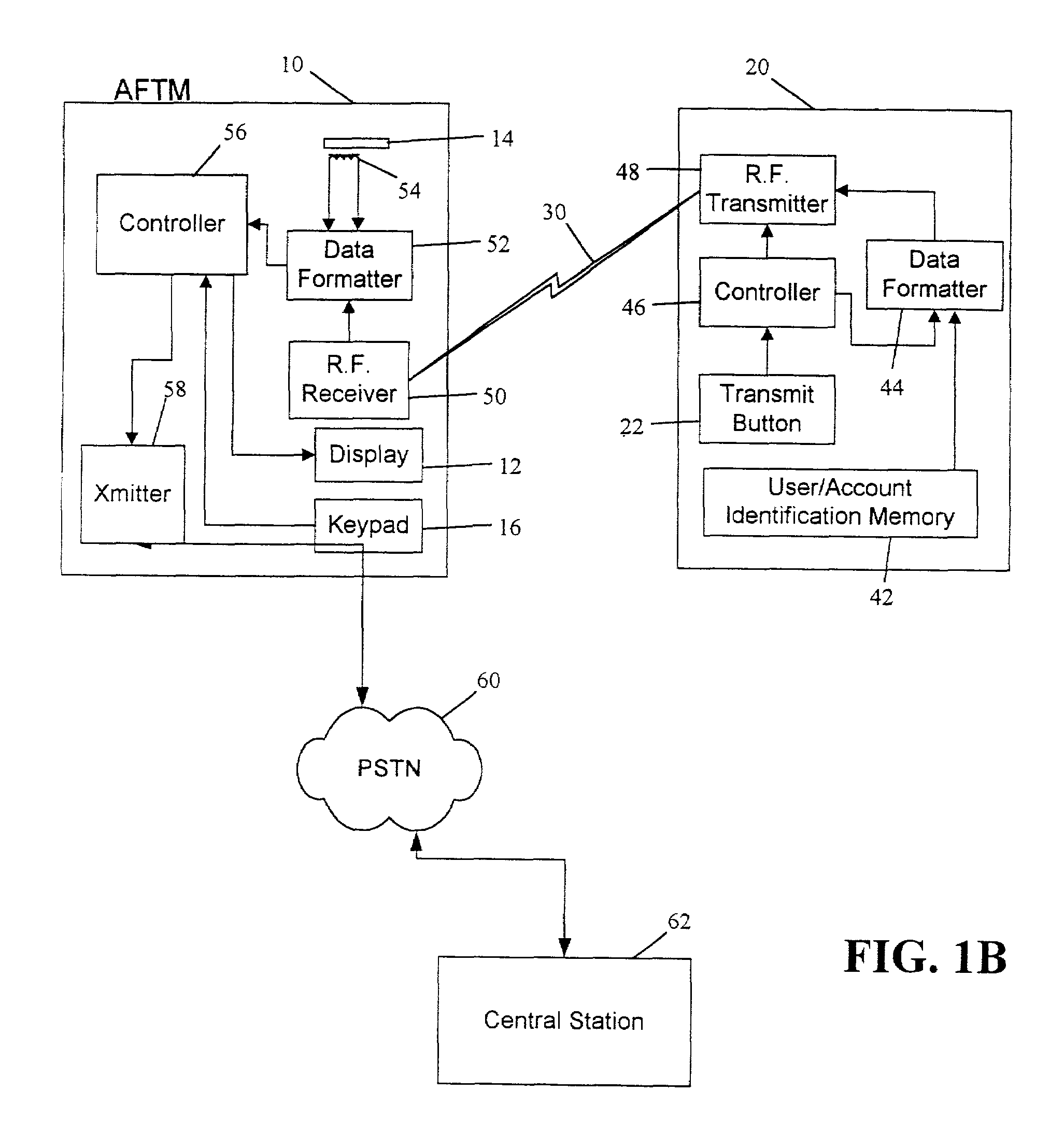
[0024]While the present invention is broadly directed to a general purpose transceiver and a method for communicating information from remote sites to a central location, before specifically describing these aspects of the invention, reference will first be made to two different illustrative environments and uses of the present invention In this regard, FIGS. 1A and 1B illustrate an environment in which information may be communicated from financial transaction machines (e.g., ATMs) to a c...


PUM


Abstract

The present invention is generally directed to a system and associated method for communicating information to a predetermined location. The system includes a transmitter disposed at a first location and configured to transmit a signal containing an instruction code that uniquely identifies an instruction to be carried out. The system further includes a transceiver disposed remotely from the transmitter and configured to receive the transmitted signal. The transceiver circuit includes a line interface circuit configured to interface with a telephone line that is part of the public switched telephone network (PSTN) and initiate a phone call over the telephone line. Finally, the system includes a central station remotely located from said transceiver but being in communication with said transceiver via the PSTN The central station further include a decoder configured to decode the instruction code. In accordance with a broader aspect, the invention is directed to a general purpose transceiver having a receiver for receiving an information signal and a transmitter configured to transmit an outgoing signal over a phone line to a central station A portion of the information signal includes an instruction code, which may be decoded by the central station and acted upon accordingly Consistent with the general purpose nature of the transceiver, the phone number of the central station may be transmitted to the transceiver as part of the information signal.

Description

CROSS-REFERENCE TO RELATED APPLICATIONS[0001]This application is a continuation of U.S. application Ser. No. 09 / 102,399 filed Jun. 22, 1998 now U.S. Pat. No. 6,233,327 which is a continuation-in-part of U.S. patent applications Ser. Nos. 08 / 825,576, filed on Mar. 31, 1997, entitled Transmitter for Accessing Automated Financial Transaction Machines, 08 / 895,720, filed Jul. 17, 1997 now U.S. Pat. No. 5,926,531, entitled Transmitter for Accessing Pay-Type Telephones, and 08 / 910,980, filed Aug. 7, 1997, entitled Transmitter for Automatically Communicating Information to a Telephone, which all claimed the benefit of U.S. provisional patent application Ser. No. 60 / 040,316, filed Feb. 14, 1997, and entitled Card Replacement Transceiver for Use With Automatic Teller Machines This application further claims the benefit of U.S. provisional patent application Ser No. 60 / 059,643, filed Sep. 20, 1997, and entitled System For Requesting Service Of A Vending Machine.BACKGROUND OF THE INVENTION[0002...

Claims


Application Information

Patent Timeline
IPC IPC(8): H04M17/00G06Q20/02G06Q20/04G07F5/18G07F7/00G07F9/02
CPCG06Q20/02G06Q20/04G07F5/18H04M11/00G07F11/002G07F17/0014G07F9/02H04W76/10H04W52/0209G07F9/002Y02D30/70G07F9/001H04W40/02
Inventor PETITE, THOMAS D.
Owner STATSIGNAL IPC
Learn More