
Tubeless fiber optic cables having strength members and methods therefor

a technology of fiber optic cables and strength members, which is applied in the direction of optics, fibre mechanical structures, instruments, etc., can solve the problems of limiting the high-bandwidth capacity of optical fiber links to the subscriber, copper cables have drawbacks, and transmit relatively limited data, so as to inhibit distortion and/or influence the cross-sectional shape of tubeless cables

Active Publication Date: 2008-07-08
CORNING OPTICAL COMM LLC
View PDF1 Cites 22 Cited by
  • Summary
  • Abstract
  • Description
  • Claims
  • Application Information

AI Technical Summary

Benefits of technology

The present invention relates to tubeless fiber optic cables and methods of making them. The invention addresses the problem of distortion and cross-sectional shape of the cable caused by torsional forces from strength members. The invention provides a solution by using a cable jacket that has a cavity along a longitudinal axis of the cable, with the first and second strength members disposed on opposite sides of the cavity. The strength members have a construction that includes a plurality of strands, with one strength member having a torsional force in one direction and the other strength member having a torsional force in the opposite direction. This intentionally distorts the cross-sectional shape of the cavity to allow more ribbons within the cable. The invention also provides a method for making the strength member by inducing twists in the strands in opposite directions. The technical effects of the invention are improved strength and stability of the fiber optic cable, reduced distortion and improved cross-sectional shape, and increased efficiency of the cable construction process.

Problems solved by technology

However, copper cables have drawbacks because they are large, heavy, and can only transmit a relatively limited amount of data compared with optical waveguides such as optical fiber.
However, most communication networks still use copper cables for drop links on the subscriber side of the central office, thereby limiting the high-bandwidth capacity of the optical fiber links to the subscriber.
But certain obstacles exist that make it challenging, time-consuming, and / or expensive to route optical fiber to the subscriber.

Method used


Image

  • Tubeless fiber optic cables having strength members and methods therefor
  • Tubeless fiber optic cables having strength members and methods therefor
  • Tubeless fiber optic cables having strength members and methods therefor

Examples


Embodiment Construction

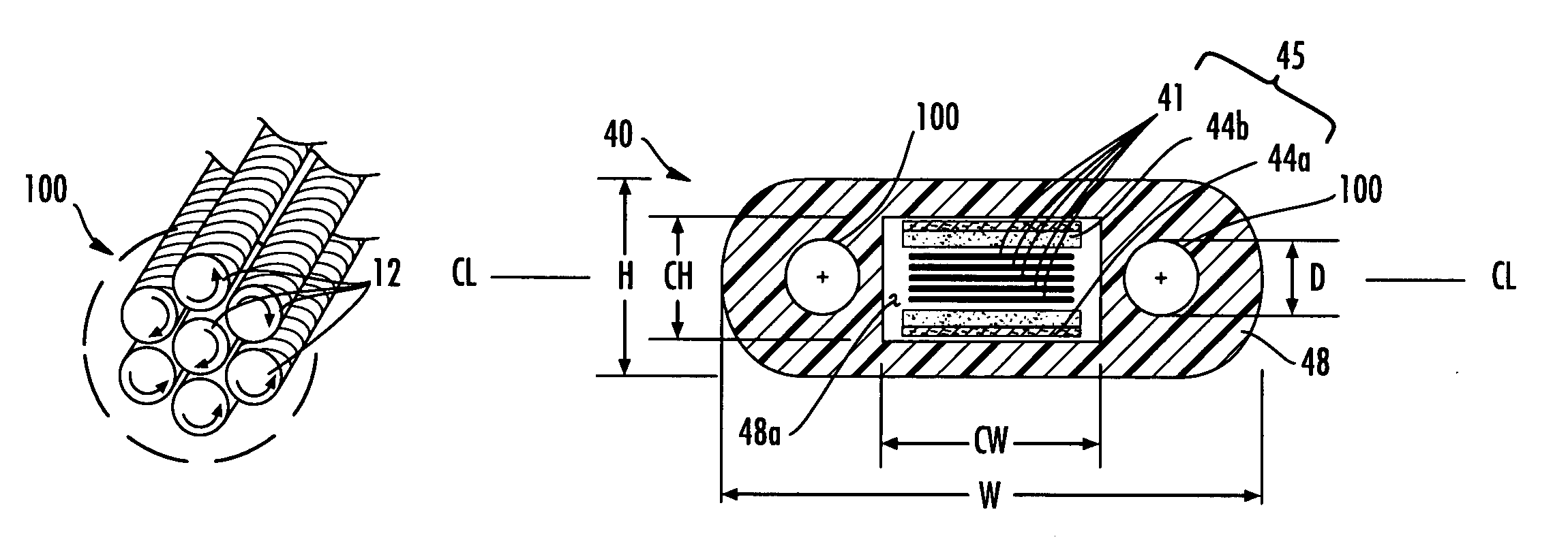
[0026]Reference will now be made in detail to the present preferred embodiments of the invention, examples of which are illustrated in the accompanying drawings. Whenever practical, the same reference numerals will be used throughout the drawings to refer to the same or like parts. Tubeless fiber optic cables of the present invention are different that fiber optic cables having tubes such as mono-tube or loose-tube constructions because tubeless fiber optic cables eliminate the mono-tube or loose tubes, thereby making them less stable during manufacturing and susceptible to distortion or deformation. This is especially true for generally flat cable design with relatively large cavities compared to the overall cable cross-section. In other words, the tube or tube assembly helps stabilize and support the cross-sectional shape of the jacket during manufacturing and removing the same removes the stability and support for the cable jacket, thereby making manufacturing more difficult. Mor...


PUM


Abstract

Disclosed are tubeless fiber optic cables having strength members, methods of making the cables, and methods for making strength members. Specifically, the concepts of the invention inhibit the distortion and / or influence the cross-sectional shape of the tubeless fiber optic cables due to torsional forces from the strength members. For instance, one tubeless fiber optic cable of the invention uses strength members with a dead-lay construction for inhibiting distortion of the same. Another tubeless fiber optic cable design uses strength members on opposite sides of the cavity where the torsional forces from the strength members are in opposite directions for influencing the cross-sectional shape of the same. Other aspects of the invention are directed to methods for making the tubeless fiber optic cables.

Description

FIELD OF THE INVENTION[0001]The present invention relates generally to tubeless fiber optic cables having strength members for use in outdoor and / or indoor environments, methods for making the cables, and methods for making strength members. Specifically, the invention uses concepts that inhibit the distortion and / or influence the cross-sectional shape of the tubeless fiber optic cables due to torsional forces from the strength members.BACKGROUND OF THE INVENTION[0002]Communication networks are used to transport a variety of signals such as voice, video, data transmission, and the like. Traditional communication networks use copper wires in cables for transporting information and data. However, copper cables have drawbacks because they are large, heavy, and can only transmit a relatively limited amount of data compared with optical waveguides such as optical fiber. Consequently, optical waveguide cables replaced most of the copper cables in long-haul communication network links, the...

Claims


Application Information

Patent Timeline
Patent Type & Authority Patents(United States)
IPC IPC(8): G02B6/44
CPCG02B6/4433G02B6/441G02B6/4411G02B6/4494G02B6/4475G02B6/44384
Inventor BLAZER, BRADLEY JEROMEBURNS, RODNEY MAURICEGREENWOOD, III, JULIAN LATELLEHEDRICK, DOUGLAS SCOTTTEMPLE, JR., KENNETH DARRELLWHISNANT, III, WILSON SIDNEY
Owner CORNING OPTICAL COMM LLC
Learn More