Method and apparatus for laying floors

a technology for laying floors and methods, applied in the field of floor laying methods and apparatuses, can solve the problems of unable to generate momentum with a hammer or rubber mallet, simplify the method, and achieve the effect of preventing lifting and facilitating the operation of the apparatus

Active Publication Date: 2008-07-15
VAN HORNE JR JEFFERSON
View PDF5 Cites 31 Cited by
  • Summary
  • Abstract
  • Description
  • Claims
  • Application Information

AI Technical Summary

Benefits of technology

[0007]This invention provides a method and apparatus for setting or abutting an individual floorboard or an individual section of laminate flooring to an assembled floor which is especially useful in situations where obstructions prevent the use of other setting or abutting devices or techniques. The apparatus of the invention provided includes a rod having at one end a flanged member. The flanged member has a notch in its vertical flange which, when the apparatus is in use, contacts the edge of a floorboard to be abutted. One surface of the notch contacts the top surface of the floorboard and another surface of the notch contacts the side of the floorboard. The floorboard is thereby prevented from lifting upwardly during use of the apparatus by its contact on its top surface with one surface of the notch. The rod has a weighted member slidably engaged thereon which can build momentum in a horizontal direction as it slides on the rod. An impact member is provided on said rod which serves to receive the impact of the sliding weighted member when the apparatus is in use. When the weighted member contacts the impact member, the momentum generated by the sliding weighted member is transferred in a horizontal direction to the floorboard contacted by the notch of the flanged member and the individual floorboard is thereby “set” or abutted to the assembled floor. When the term floorboard is used, it should be pointed out that this term can encompass an individual piece of laminate flooring or any other wooden flooring. The apparatus is also provided with a stabilizing ring. The stabilizing ring is connected to the rod adjacent the impact member but outside of the impact member relative to the weighted member. The stabilizing ring is preferably plastic and has minimal contact with the assembled floor during use of the apparatus. It can be easily appreciated that the stabilizing ring keeps the rod in a horizontal direction and serves in general to support the apparatus on the assembled floor when in use. A handle is also provided for easier operation of the apparatus. In operation of the apparatus, an operator can grab the handle with one hand and slide the weighted member along the rod with the other hand as the stabilizing ring rests on the assembled floor and the notch of the flanged member engages the individual floorboard to be set. Use of the apparatus insures a horizontal force being applied to the floorboard to be set without any substantial unwanted vertical or lifting force.
[0009]An object of the invention, therefore, is to provide a tool and method for setting individual floorboards which are in close proximity to an obstruction in an easy and efficient manner.
[0010]Another object of the present invention is to provide a method and tool for setting individual floorboards close to obstructions which prevent damage to the floorboards.
[0011]A further object of the present invention is to provide a tool and method for abutting a floorboard to an assembled floor near an obstruction which is relatively safe and also prevents damage to the obstruction.
[0013]A further object of the present invention is to provide a device for abutting floorboards which minimally impacts the assembled floor during normal use.

Problems solved by technology

This simple methodology fails, however, when there is insufficient space to build momentum in such a way that it can be imparted to the object in a direction that will force the object against the adjacent object.
Imparting a force becomes significantly more difficult as this area to create a force diminishes.
It is, therefore, impossible to generate momentum with a hammer or rubber mallet as you cannot swing the hammer in such a way as to impart a force in a direction that would force a wood flooring board against an adjacent wood flooring board.
Initially, the device used in the two patents contacts the floor to some degree, setting up a possibility that the assembled floor, during operation of the apparatus, could be marked or damaged in some way.
This “lifting” force on the floorboard and assembled floor is highly undesirable and is also absorbed by the device itself adding a wear component to the tool.
A further disadvantage to the above two mentioned patents is that the space required behind the floorboard to be set is greater than the present invention.
This relatively large space required is due in part to the general application of those tools.
In an application, however, such as laying a laminate tongue-in-groove hardwood wherein the tongue and groove were located at the ends of the floorboard, problems would be presented for those tools.
In particular, it is especially difficult to set the end of a laminate floorboard where that board meets a wall or other obstruction.

Method used


Image

  • Method and apparatus for laying floors
  • Method and apparatus for laying floors
  • Method and apparatus for laying floors

Examples


Embodiment Construction

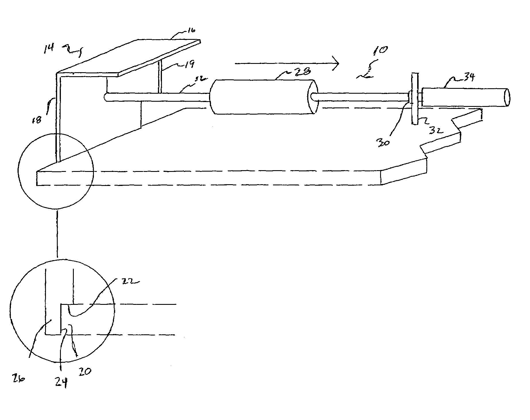
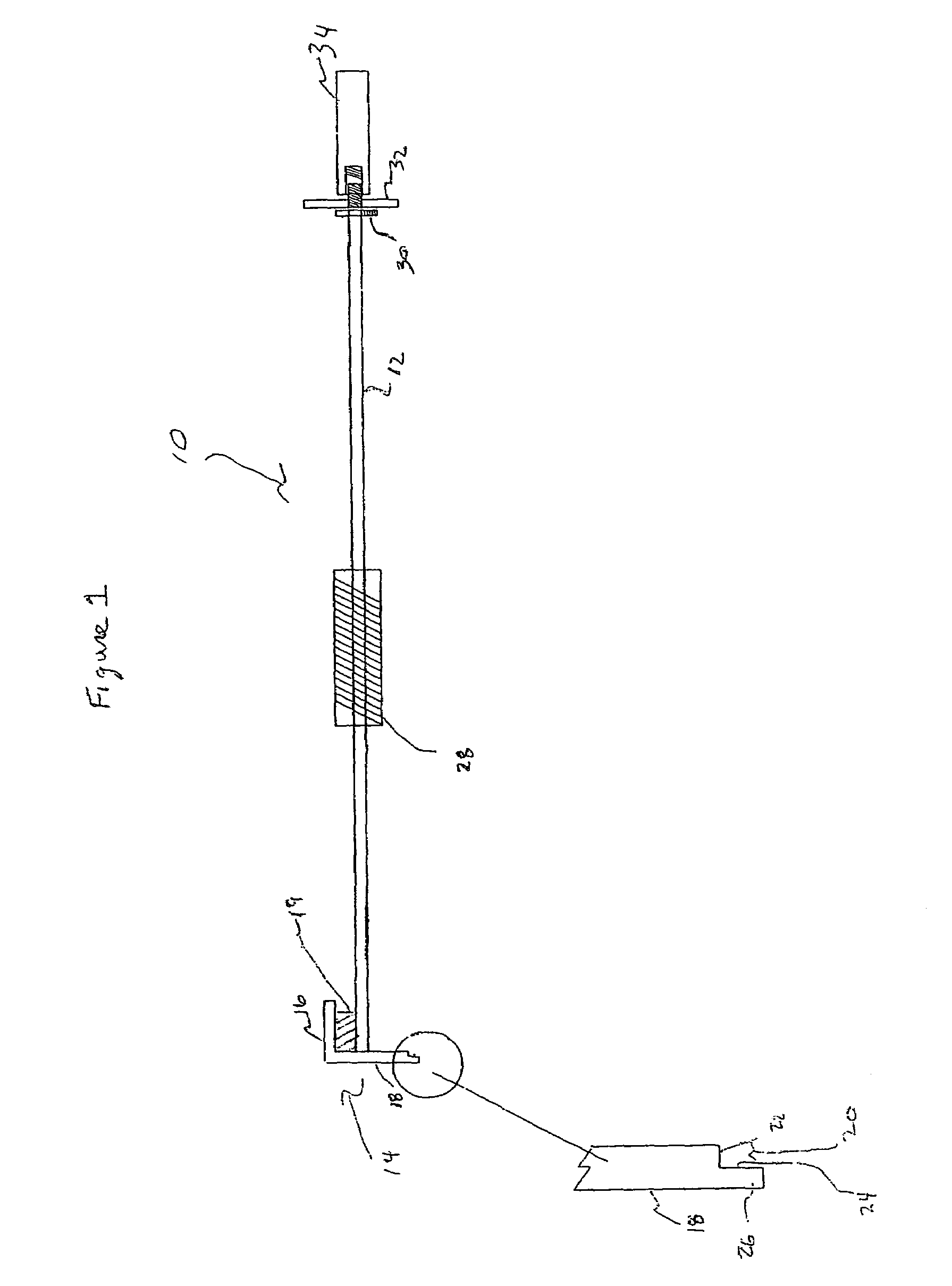
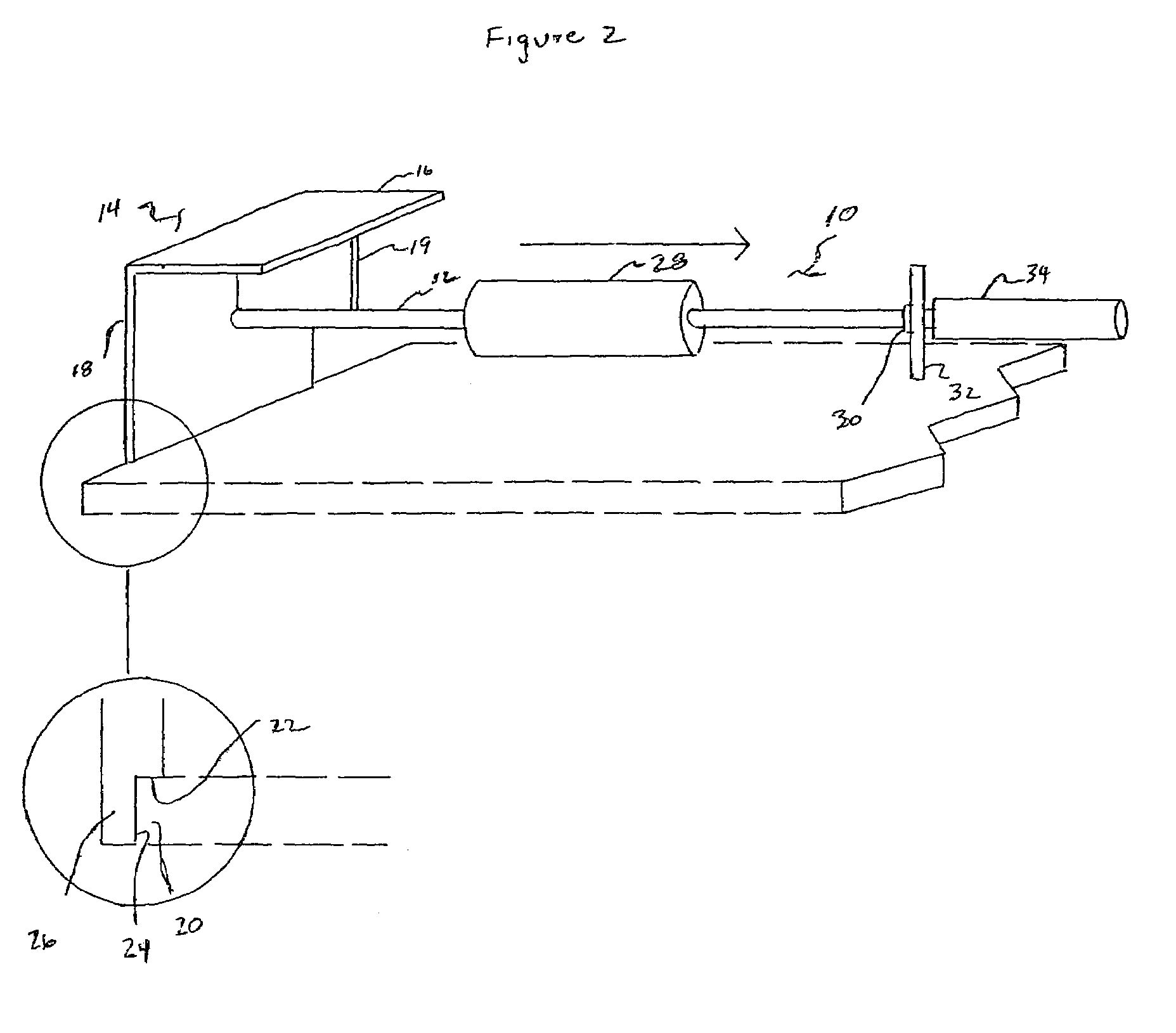
[0018]Referring to the figures, a tool 10 for abutting or “setting” individual floor panels in an assembled floor near an obstruction can be described. The tool has a rod 12 having a flange 14 attached thereto. The flange 14 has a horizontal portion 16 and a vertical portion 18. Preferably the flange 14 can be made from 2″×3″ angle iron. The rod 12 is attached to the vertical portion 18 of the flange 14. A web section 19 is welded between the rod 12 and flange 14 to add stability to the rod and flange connection. The vertical portion 18 of flange 14 has a notch, designated as 20 in the figures. Notch 20 is defined by a horizontal surface 22 in vertical portion 18 of flange 14, and a vertical surface 24 in vertical portion 18 of flange 14. The notch 20 also leaves a narrow end portion, designated as 26, at the bottom of vertical portion 18 of flange 14. To put the general dimensions in context, the end portion would preferably have a width of ⅛″.

[0019]A weighted cylindrical slide 28 ...


PUM


Abstract

A tool and method for abutting an individual floor panel which is near an obstruction, such as a wall, to the assembled floor. The tool and method provide a rod having a flanged member at one end. The flanged member has a notch in its vertical flange which contacts the floorboard to be abutted, requiring a minimal amount of space between the obstruction and floorboard to be set. A sliding weight mounted on a rod can then be slid toward an impact surface resulting in a horizontal force being applied to the individual floorboard thereby abutting or setting that floorboard with respect to the assembled floor. An especially useful application for the device and method is in the installation of a tongue-in-groove laminate floor in which the individual floorboards have a tongue and groove connection on their ends.

Description

BACKGROUND OF THE INVENTION[0001]1. Field of the Invention[0002]This invention relates in general to a tool for facilitating the laying of a floor, and more particularly to a method and device for “setting” or abutting a laminate wood floor panel adjacent to an obstruction to the previously assembled floor.[0003]2. Discussion of the Prior Art[0004]There are many ways in which to force objects which are adjacent to one another snugly together. The simplest way, of course, is to simply provide a force transverse to the length of the two objects by using a device such as a hammer or rubber mallet. This is accomplished by building up linear momentum in the hammer and then directly imparting that momentum into the side of the object by direct contact. Thus the momentum is transmitted to the object, which is then forced via the transverse momentum snugly against the adjacent object. This simple methodology fails, however, when there is insufficient space to build momentum in such a way th...

Claims


Application Information

Patent Timeline
Patent Type & Authority Patents(United States)
IPC IPC(8): E04D15/00B25D1/00B25D1/16B66F3/00E04F15/00E04F21/00E04G21/14E04F21/22
CPCE04F21/22
Inventor VAN HORNE, JR., JEFFERSON
Owner VAN HORNE JR JEFFERSON
Why Eureka
Try Eureka