Sealing ring and its managing system

a technology of sealing rings and managing systems, applied in the field of sealing rings, can solve the problems of deteriorating physical properties, changing material properties of elastic materials composing sealing rings, and affecting the product yield, so as to achieve accurate and easy management of sealing rings, accurate judgment of sealing rings life duration, and accurate knowledge

Active Publication Date: 2008-07-15
VALQUA LTD
View PDF8 Cites 26 Cited by
  • Summary
  • Abstract
  • Description
  • Claims
  • Application Information

AI Technical Summary

Benefits of technology

[0088]As to the sealing ring according to the present invention, it is possible to accurately know or judge such as the performance property, life duration, and exchange timing about each sealing ring (which is used in the fitted place) by the information transmission between the circuit chip (attached unitedly to the main body part) and the outside of the sealing ring.
[0089]Particularly, if the circuit chip has the sensor part, then the physical or chemical state quantity of the sealing ring that is actually used can be detected, and the usage environment conditions of the sealing ring and its progress conditions in performance deterioration can be accurately known, so that it is possible to accurately judge the life duration of the sealing ring and its exchange timing.
[0090]In addition, if the circuit chip has the information storage part, then the histories (different between individual sealing rings) of from production till during use of the sealing rings, the properties of the sealing rings, and other information necessary for managing the sealing rings can be obtained from every individual sealing ring during its use, so that it becomes possible to accurately and easily manage the sealing rings.

Problems solved by technology

Under general use conditions of the sealing ring, it is inevitable that an elastic material composing the sealing ring changes in material property or deteriorates in physical property with the passage of time.
For example, a sealing ring to be attached to a valve of a semiconductor-producing device and its opening-and-closing cover is used under severe conditions such that: high air tightness is required, a load applied upon using is large, and further, the sealing ring has a possibility of contacting with a plasma gas or a corrosive gas.
If the use of the sealing ring with the deteriorated performance is continued, a quality performance of a semiconductor product is damaged to thus deteriorate the product yield.
As to conventional methods to judge the exchange of the sealing ring or to manage the sealing ring, it is difficult to appropriately judge the exchange or make strict management about individual sealing rings when they are used.
For example, as to the art described in the above patent document 1, unless the O-ring is fetched out from its fitting part to observe its surface, it is not possible to judge the deterioration of the O-ring from whether the inner signal member is exposed or not.
During this time, a time loss is large and a human burden is also heavy.
However, unless there is any past data such that the load and environmental conditions, acting on the sealing ring, conform completely to those of the present sealing ring, it is difficult to accurately estimate the exchanging timing.
It has a limitation to estimate a degree of progress in a deterioration of a performance and a life duration about each of the sealing rings by only the data collected in the past.
However, this results in also exchanging the sealing ring having a sufficient sealing function, so this leads to much waste of money.
The number of times of the exchanging of the sealing ring increases more than necessary, so that unfavorably the operation rate of the apparatus to which the sealing ring is attached decreases largely.
This is very troublesome.
It is very troublesome to give an identification number to each sealing ring and record it every time the sealing ring is attached or exchanged on the scene using the sealing ring.
As to a sealing ring in use incorporated within the equipment and apparatus, it is difficult to check, from the outside, which identification number this sealing ring has.

Method used


Image

  • Sealing ring and its managing system
  • Sealing ring and its managing system
  • Sealing ring and its managing system

Examples


Embodiment Construction

[0112]Hereinafter, detailed descriptions are given about the present invention. However, the scope of the present invention is not bound to these descriptions. And other than the following illustrations can also be carried out in the form of appropriate modifications of the following illustrations within the scope not departing from the spirit of the present invention.

[0113][Use Mode of O-Ring]:

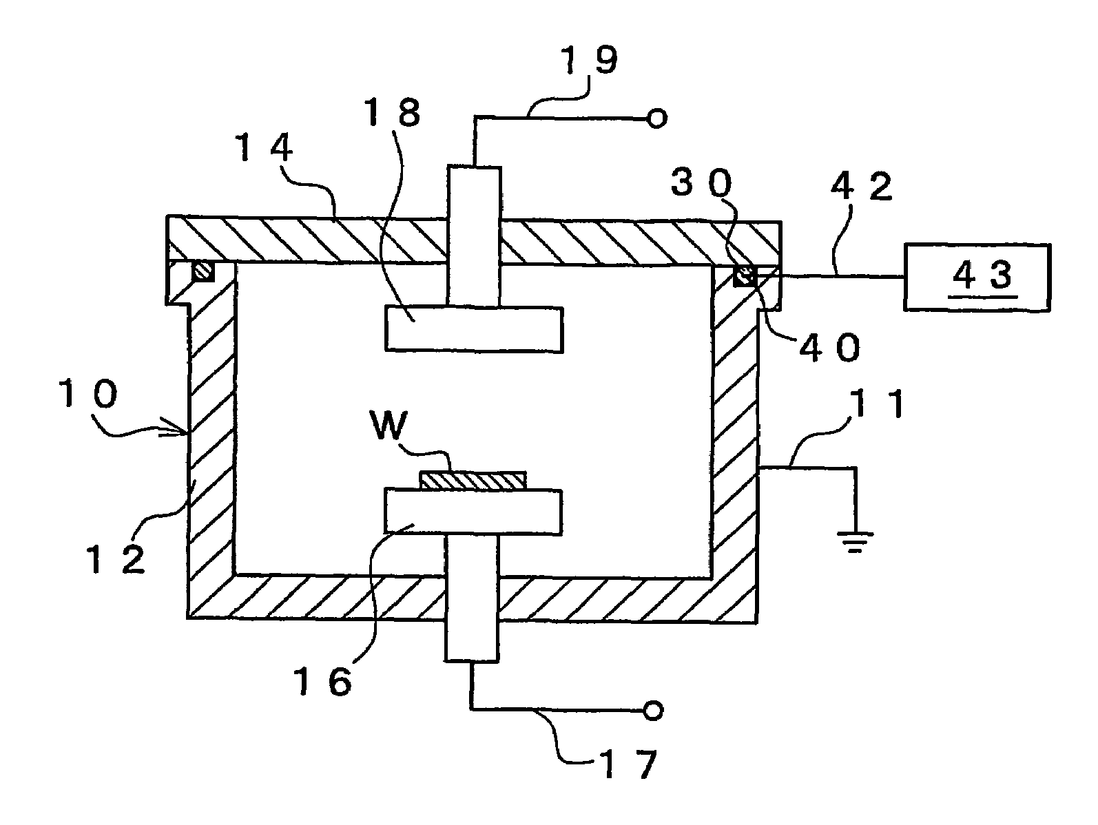
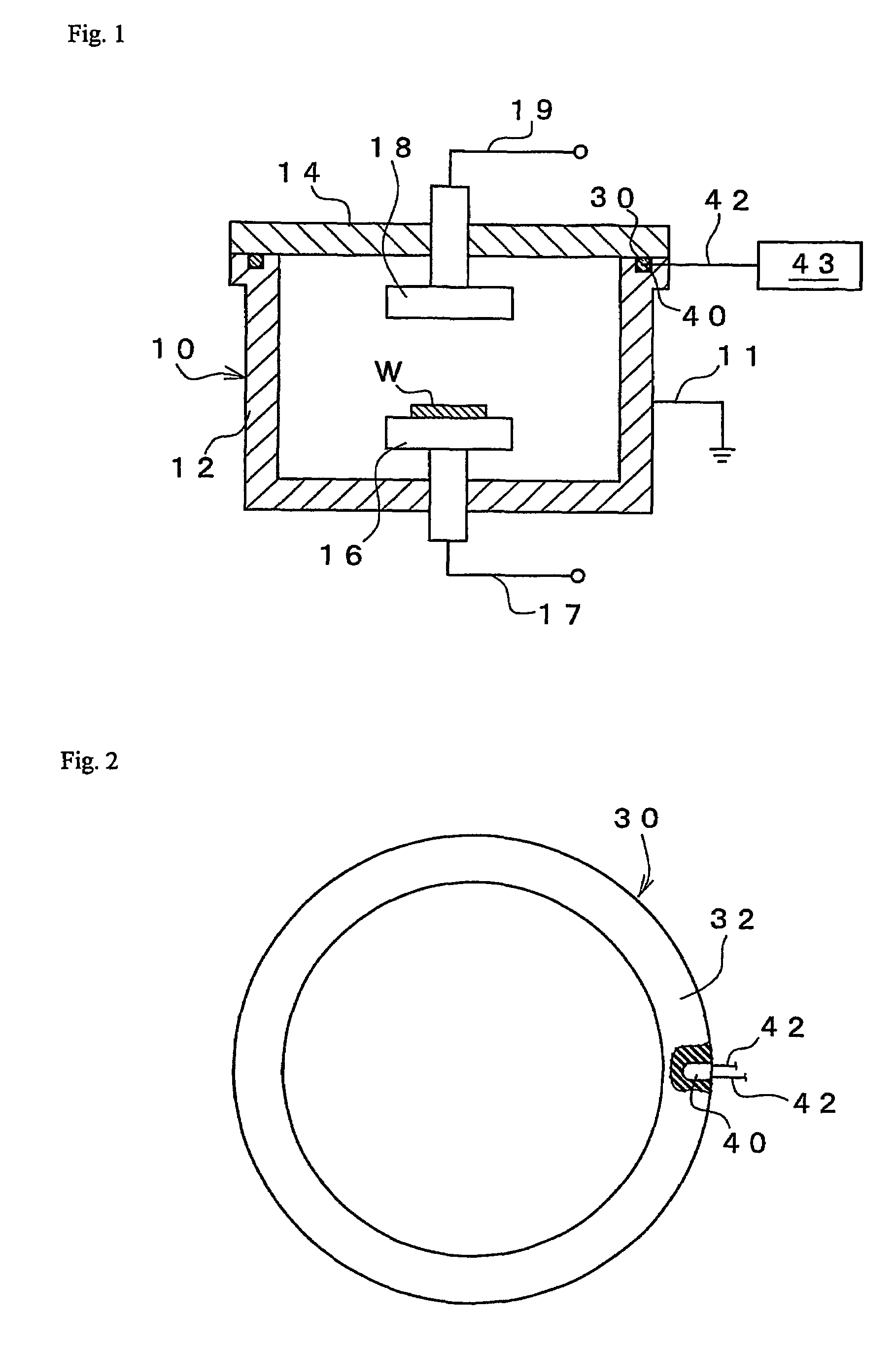
[0114]The mode for carrying out the present invention, as illustrated in FIG. 1, shows a state where an O-ring 30, which is a sealing ring, is used in a semiconductor-producing apparatus 10.

[0115]In the semiconductor-producing apparatus 10, a cover body 14 that is freely openable and closeable is attached on a top surface of a container-shaped processing chamber 12. In the processing chamber 12 and under the cover body 14, electrodes 16 and 18 are disposed respectively. To the electrodes 16 and 18, wirings 17 and 19 leading to a power source are connected respectively. To the processing chamb...


PUM

PropertyMeasurementUnit
diameteraaaaaaaaaa
temperatureaaaaaaaaaa
inner stressaaaaaaaaaa

Abstract

An object of the present invention is to make it possible to accurately and simply manage the performance deterioration and life duration of sealing rings and other various information about each sealing ring. As a means of achieving this object, a sealing ring according to the present invention is a sealing ring 30 to be fitted to a face-to-face part of members 12, 14 to thus seal a space between both members, comprising: a main body part 32 that is ring-shaped and is capable of becoming elastically deformed; and a circuit chip 40 that is attached unitedly to the main body part 32 and has an information-transmitting means 42 for transmitting the information with the outside of the sealing ring 30.

Description

[0001]This is the U.S. national phase of International Application No. PCT / JP2004 / 014432, filed Sep. 24, 2004, which claims priority from Japanese Patent Application No. 2003-338541 filed Sep. 29, 2003.TECHNICAL FIELD[0002]The present invention relates to a sealing ring. Specifically, the present invention relates to: a sealing ring which is to be fitted to a face-to-face part of members to thus serve to seal a space between both members in such as vacuum devices and piping instruments required to have high air tightness; and a managing system for such a sealing ring.BACKGROUND ART[0003]As a typical sealing ring, an O-ring is known. The O-ring is molded in a ring shape with an elastic material such as rubber, and its section is O-shaped. Depending on a required performance and a use, various sealing rings having sectional shapes different from that of the O-ring are also proposed.[0004]The sealing ring typified by the O-ring is used in places where a sealing function such as air tig...

Claims


Application Information

Patent Timeline
Patent Type & Authority Patents(United States)
IPC IPC(8): G01L7/00F16J15/00F16J15/06F16J15/10
CPCF16J15/064F16J15/3296F16J15/104
Inventor HIROKI, TSUTOMUNOGUCHI, MASAYUKISAKURAI, SHINYA
Owner VALQUA LTD
Why Eureka
Try Eureka