Phase-locked loop circuit

a phase-locked loop and circuit technology, applied in the direction of logic circuit pulse generation, oscillator generator, pulse automatic control, etc., can solve the problem that the frequency of the output signal cannot be identified with a high degree of accuracy, and achieve accurate switching, accurate knowledge, and extended output frequency range

Inactive Publication Date: 2010-03-04
RENESAS ELECTRONICS CORP
View PDF3 Cites 24 Cited by
  • Summary
  • Abstract
  • Description
  • Claims
  • Application Information

AI Technical Summary

Benefits of technology

[0008]According to an exemplary embodiment of the present invention, the frequency of the output pulse signal can be accurately known by detecting the control current. Therefore, the frequency range of the output pulse signal can be accurately switched. Thus, the output frequency range can be extended.
[0009]According to an exemplary embodiment of the present invention, it is possible to provide a phase-locked loop circuit having wide output frequency range.

Problems solved by technology

Therefore, the frequency of the output signal cannot be identified with a high degree of accuracy even when the control voltage is detected.

Method used


Image

  • Phase-locked loop circuit
  • Phase-locked loop circuit
  • Phase-locked loop circuit

Examples


first exemplary embodiment

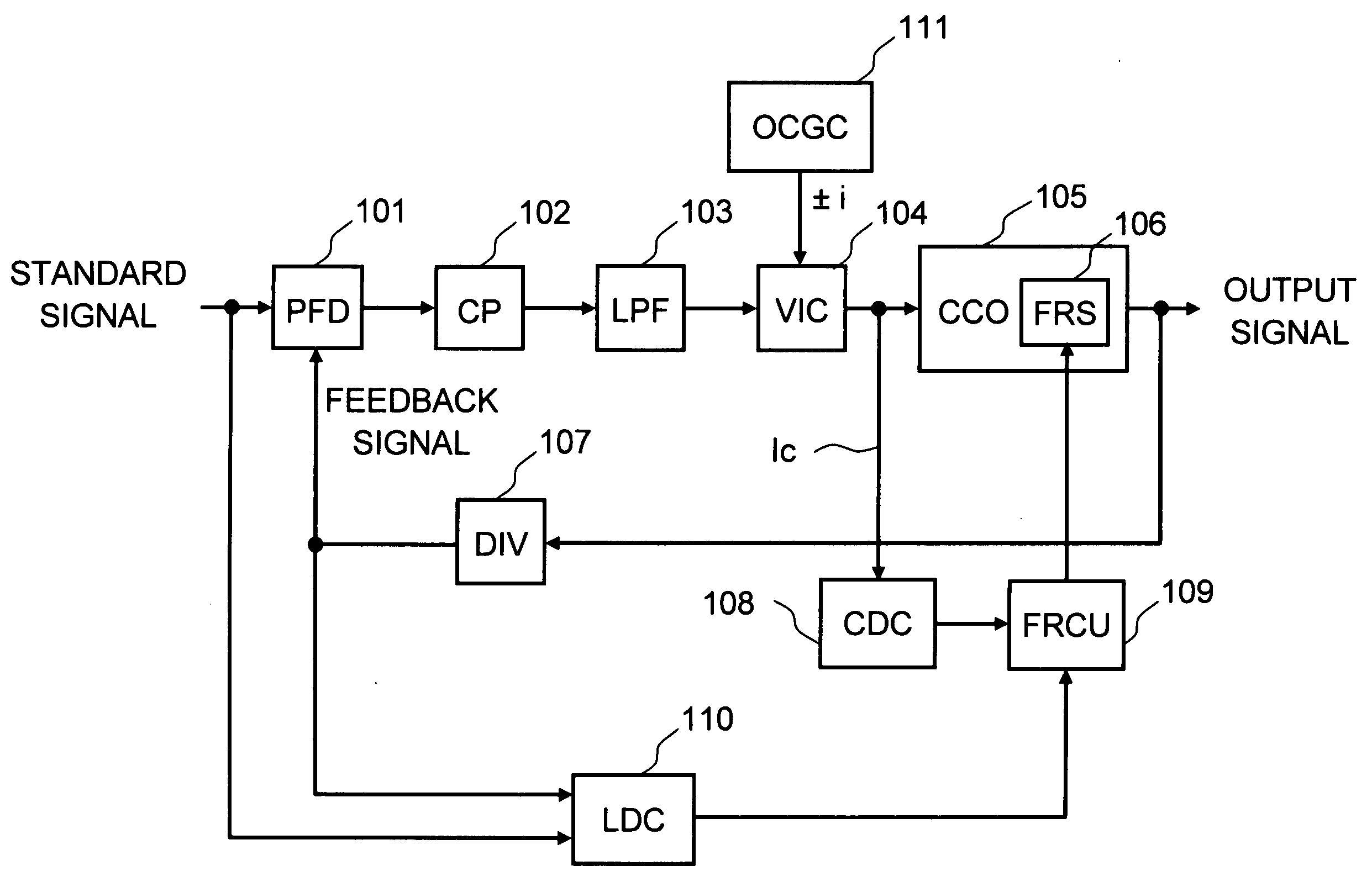
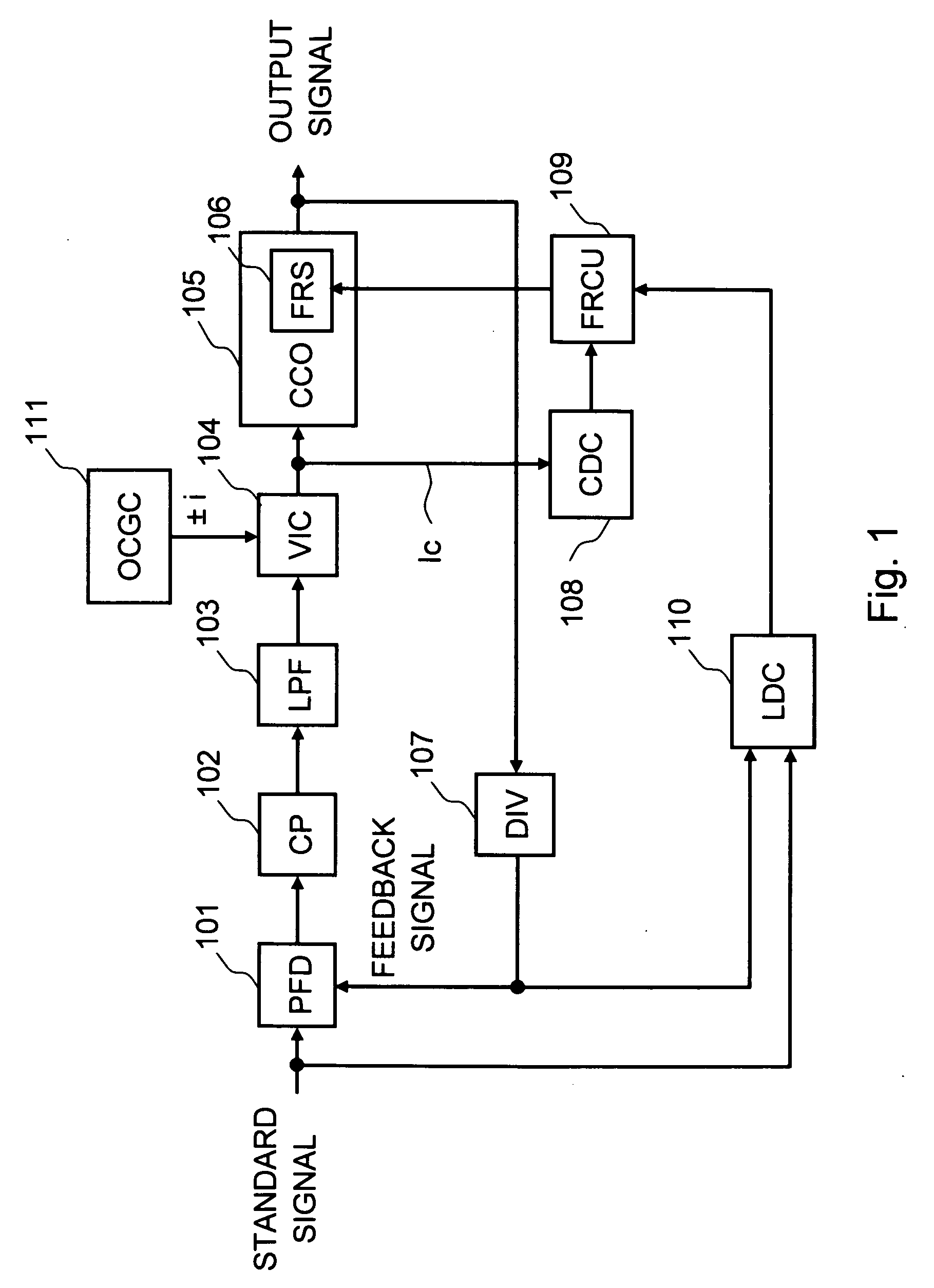
[0018]Exemplary embodiments of the present invention will be described below with reference to the accompanying drawings. FIG. 1 is a block diagram showing a PLL circuit according to a first exemplary embodiment of the present invention. As shown in FIG. 1, the PLL circuit according to the first exemplary embodiment includes a phase frequency detector (PFD) 101, a charge pump (CP) 102, a low pass filter (LPF) 103, a voltage-current converter (VIC) 104, a current controlled oscillator (CCO) 105, a frequency range switch (FRS) 106, a frequency divider (DIV) 107, a current decision circuit 108, a frequency range control unit 109, a lock detection circuit 110, and an offset current generation circuit 111.

[0019]The PFD 101 compares a phase of a feedback signal from an output side with a phase of a standard signal. When the feedback signal has a phase delayed compared to that of the standard signal, the PFD 101 outputs an UP signal to increase an oscillation frequency to the charge pump 1...

second exemplary embodiment

[0046]Next, another exemplary embodiment of the present invention will be described. The FRS 106 in the CCO 105 of the second exemplary embodiment is different from that of the first exemplary embodiment. The other components are similar to those of the first exemplary embodiment. FIG. 6 is a circuit diagram showing the current controlled oscillator 105 in the PLL circuit according to the second exemplary embodiment. The FRS 106 is composed of a plurality of capacitors and switches in the second exemplary embodiment while the FRS 106 is a frequency divider in the first exemplary embodiment.

[0047]The oscillator in the CCO 105 is the ring oscillator. In FIG. 6, the ring oscillator includes three inverters INV 1 to INV 3. Each inverter transmits a pulse signal with delay according to the control current Ic. In other words, the output frequency is controlled by the control current Ic. Here, an inverter is one example of a delay element. Thus other delay elements can be used. Further, th...


PUM


Abstract

A first exemplary aspect of an embodiment of the present invention is a phase-locked loop circuit including: a voltage-current converter that converts a control voltage into a control current, the control voltage generated according to a phase difference between an input pulse signal and a feedback pulse signal fed back from an output side of a current controlled oscillator; the current controlled oscillator that generates an output pulse signal having a frequency according to the control current; a current detection unit that detects the control current; and a frequency range switch that switches a frequency range of the output pulse signal according to the detected control current.

Description

BACKGROUND[0001]1. Field of the Invention[0002]The present invention relates to a phase-locked loop circuit.[0003]2. Description of Related Art[0004]A PLL (phase-locked loop) circuit is one of the most popular clock generating circuits. FIG. 7 shows a PLL circuit disclosed in FIG. 1 of International Patent Publication No. WO 99 / 19987. This PLL circuit includes a phase frequency detector (PFD) 14, a loop filter 18, a voltage controlled oscillator (VCO) 20, a clock divider 22, a decision circuit 30, and a control unit 32. In this PLL circuit, an input signal is input to the PFD 14. The PFD 14 generates a signal based on both the input signal and a feedback signal from an output side of the VCO 20, and outputs the generated signal to the loop filter 18. Then, the VCO 20 outputs the output signal based on a control voltage which is output from the loop filter 18. The output signal is fed back to the PFD 14 through clock divider 22.[0005]Further, the decision circuit 30 detects the contr...

Claims


Application Information

Patent Timeline
Patent Type & Authority Applications(United States)
IPC IPC(8): H03L7/00
CPCH03L7/0995H03L2207/06H03L7/10H03L7/104
Inventor HIRAI, YOSHITAKA
Owner RENESAS ELECTRONICS CORP
Why Eureka
Try Eureka