
System for mounting a hollow post about a pipe

a technology of hollow posts and posts, which is applied in the direction of pillars, building components, structural elements, etc., can solve the problems of requiring substantial effort, materials and/or time, and requiring a series of equally elevated horizontal support surfaces over a distan

Active Publication Date: 2008-07-15
STRAIGHTN LEVEL FENCING SOLUTIONS
View PDF14 Cites 13 Cited by
  • Summary
  • Abstract
  • Description
  • Claims
  • Application Information

AI Technical Summary

Benefits of technology

"The invention provides a system for mounting a hollow post about a pipe using a lower mounting device and an upper mounting device. The lower mounting device is positioned about the pipe and has a base with an opening for the pipe to pass through. The upper mounting device is positioned about the pipe and can be adjusted to different heights. The system allows for easy adjustment of the hollow post's position and stability, and can be used with different sizes of posts. The system also includes a mechanism for securely positioning the hollow post relative to the pipe, and a mechanism for interlocking the upper mounting device with the lower mounting device to secure the hollow post in place."

Problems solved by technology

Installation of a series of posts to create a substantially horizontal rail assembly may prove difficult in situations where the ground surface features irregularities that deviate from the horizontal, as the support surfaces for some base plates may have to be built up from or recessed into the ground to support neighbouring posts at a common elevation.
For the reasons provided in the preceding paragrapsh, providing a series of equally elevated horizontal support surfaces over a distance may require substantial effort, materials and / or time.

Method used


Image

  • System for mounting a hollow post about a pipe
  • System for mounting a hollow post about a pipe
  • System for mounting a hollow post about a pipe

Examples


Embodiment Construction

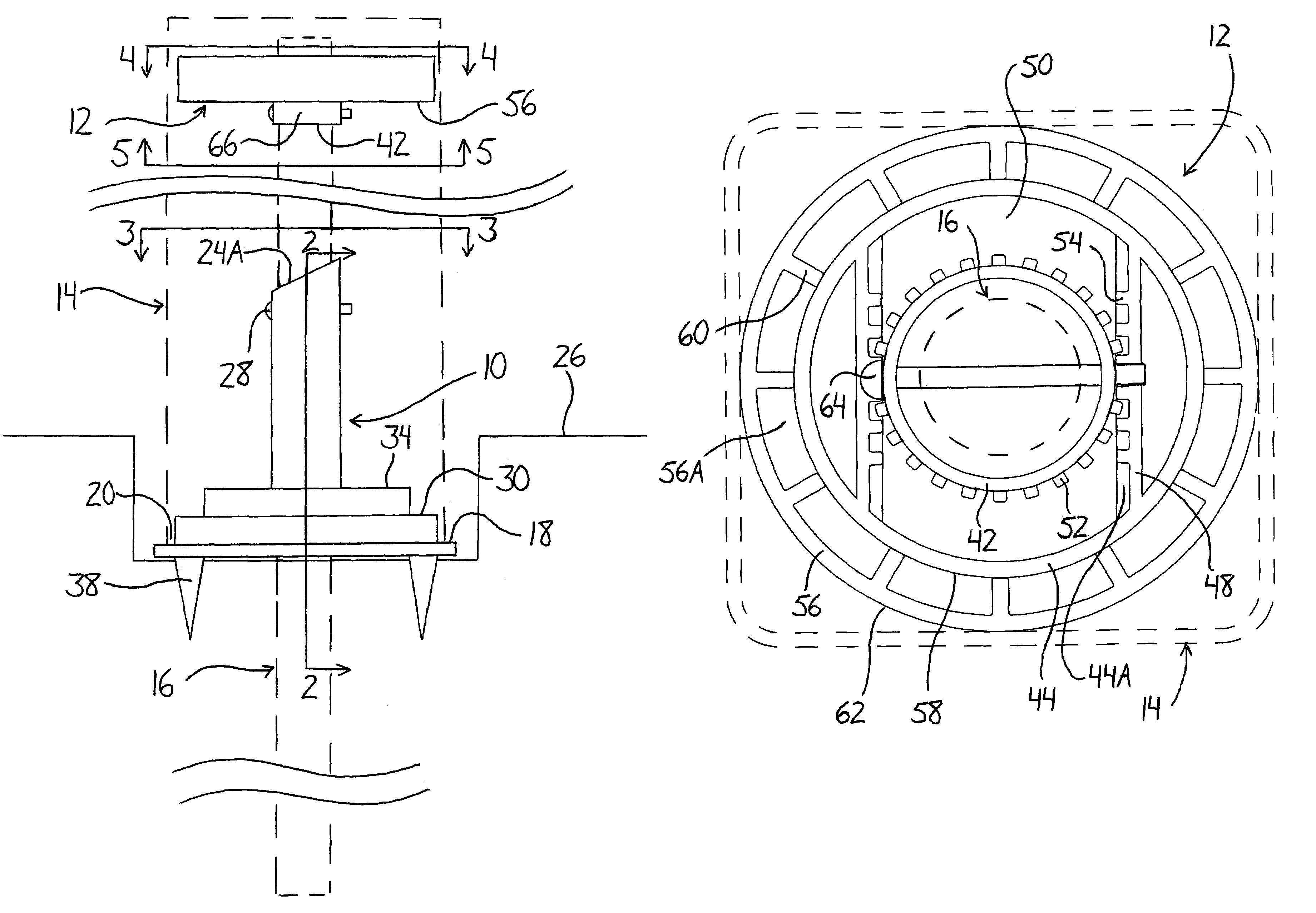
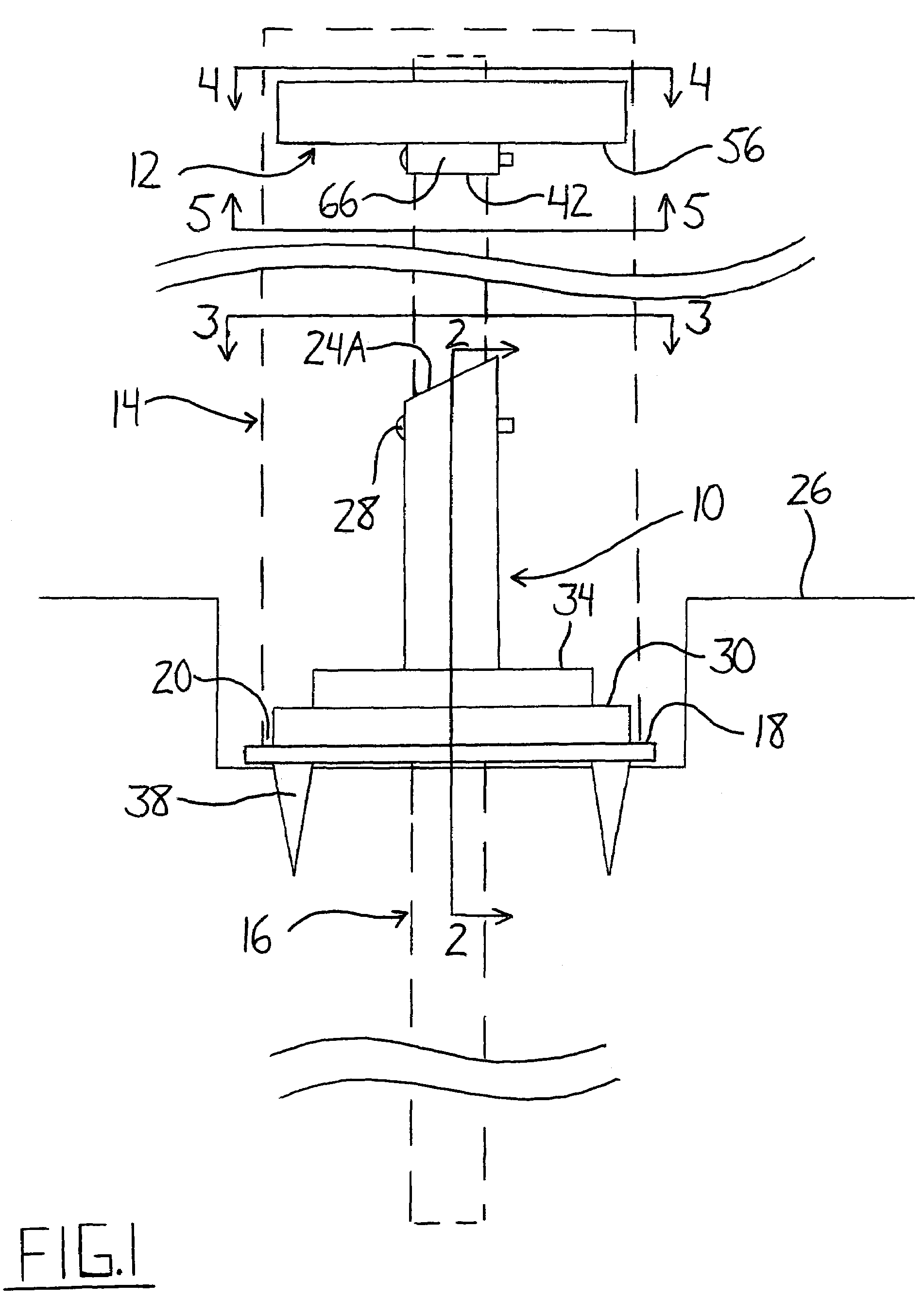
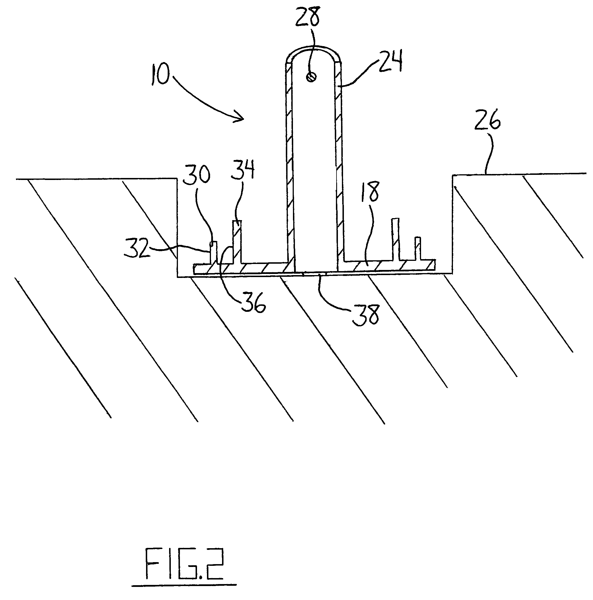
[0046]As shown in FIG. 1, a system for mounting a hollow post about an upward extending pipe features a lower mounting device 10 and an upper mounting device 12. The lower mounting device 10 defines a base on which the hollow post, represented by broken lines generally indicated at 14, rests when lowered over the pipe, represented by broken lines generally indicated at 16. The lower mounting device 10 is movable up and down along the pipe 16 before being fastened thereto such that an installer can adjust the height at which the hollow post 14 is disposed. The upper mounting device 12 allows adjustment of an angle between longitudinal axes of the pipe 16 and hollow post 14 to allow vertical alignment of the post even if the pipe 16 is not installed in perfect vertical orientation. The upper mounting device of the illustrated embodiment allows adjustment of this relative tilt after installation of the hollow post without requiring removal thereof from about the pipe to re-expose the u...


PUM


Abstract

A system for mounting a hollow post about a pipe features upper and lower mounting devices vertically spaced along the pipe. The lower mounting device is slidable along the pipe to define a height at which the hollow post sits atop a base of the lower mounting device. The lower mounting device is mountable on the pipe to allow control over the post height with minimal ground surface preparation. The upper mounting device features two members that are engagable in a number of different relative positions to allow relative positioning of the pipe and post, to each of which a respective one of the two members is engaged. In one embodiment, engagement of the members to separate ones of the post and pipe allows adjustment of the post's position relative to the pipe after installation without removal of the post for access to the upper mounting device.

Description

[0001]This invention relates to a system for mounting a hollow post about a pipe and more particularly relates to a system having upper and lower mounting devices supported on the pipe at spaced heights therealong to engage the hollow post.BACKGROUND OF THE INVENTION[0002]Plastic or vinyl rail assemblies, for example for use in fencing and decking, are gaining popularity due to their durability and pleasant appearance. Unlike wood used in conventional fencing or decking rail assemblies, the plastic or vinyl components do not require post-sale painting and weatherproofing and will not rot over time. Rail assemblies feature horizontal rails supported on and extending between vertical posts spaced apart along a straight line. Plastic or vinyl posts are usually manufactured to be hollow, and as such are usually fitted over and supported about rigid pipes that provide the necessary strength to support the final structure. The rigid pipe may be supported by driving a lower end thereof a d...

Claims


Application Information

Patent Timeline
Patent Type & Authority Patents(United States)
IPC IPC(8): E04C3/30E04H17/22
CPCE04H12/2253Y10S256/05E04F2011/1897
Inventor FROESE, JOSEPH S.
Owner STRAIGHTN LEVEL FENCING SOLUTIONS
Learn More