

Releasable mounting apparatus and trolling motor assembly
a technology of mounting apparatus and trolling motor, which is applied in the direction of marine propulsion, vessel construction, application, etc., can solve the problems of prone to rattling and other problems, difficult installation and removal of the motor, and tedious and difficult installation and removal
- Summary
- Abstract
- Description
- Claims
- Application Information
AI Technical Summary
Benefits of technology
Problems solved by technology
Method used
Image

Examples
Embodiment Construction
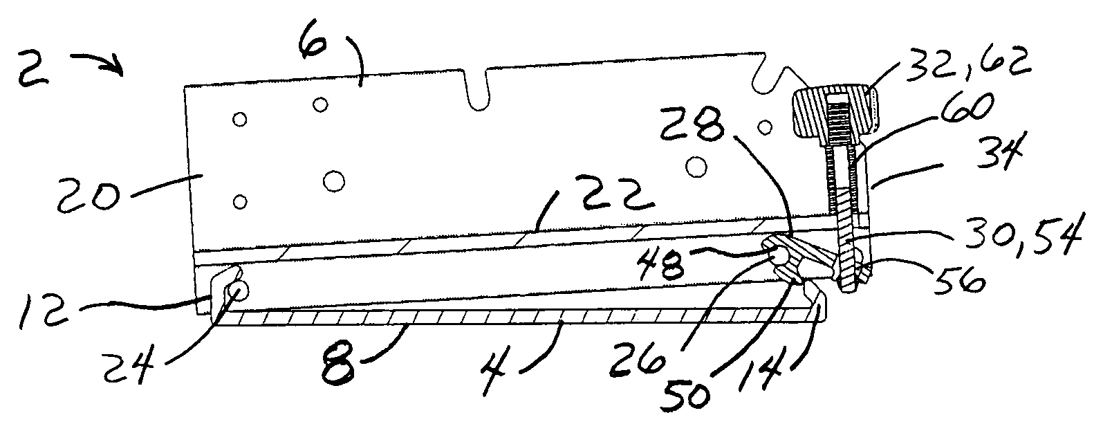
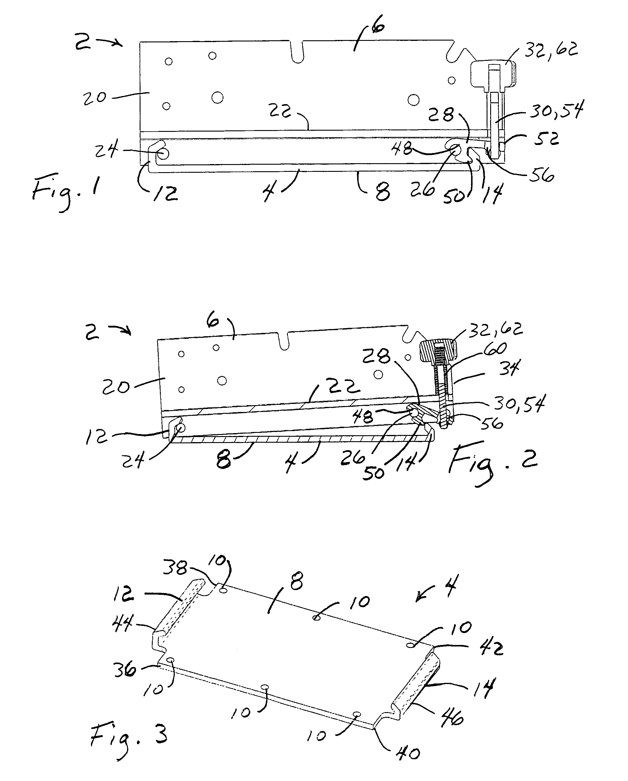
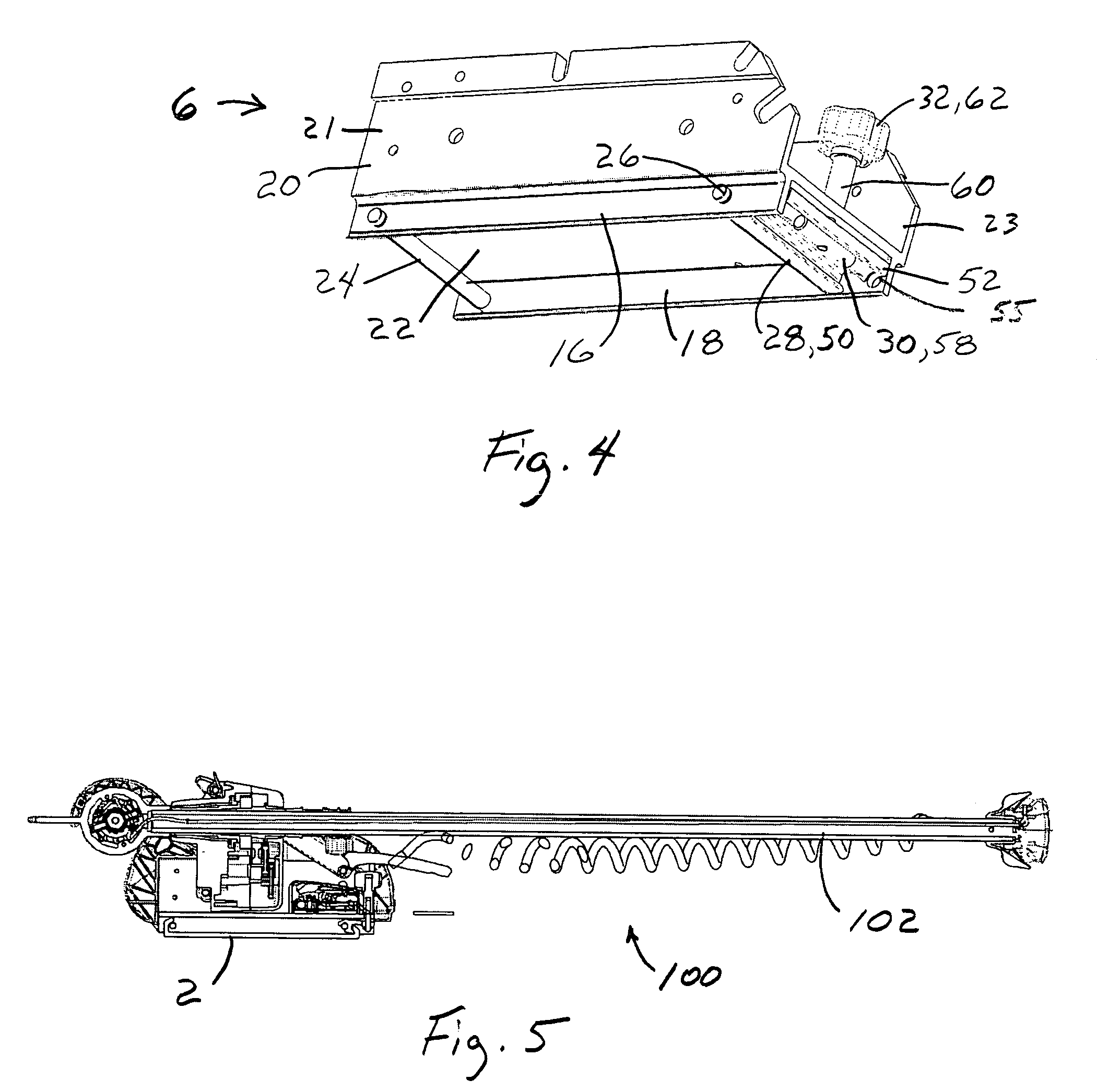
[0016]An embodiment 2 of the inventive apparatus for releasably mounting a trolling motor on a watercraft is illustrated in FIGS. 1-4. The inventive mounting apparatus 2 comprises a mounting bracket 4 and a locking assembly 6 which is releasably attachable to the mounting bracket 4. Although the attachment positions of the components of the inventive mounting apparatus 2 can be reversed, the mounting bracket 4 will preferably be secured to the watercraft and the locking assembly 6 will preferably be attached to the trolling motor. An embodiment 100 of the inventive trolling motor assembly comprising the inventive mounting apparatus 2 and a trolling motor 102 is shown in FIG. 5. The trolling motor 102 is shown in a stowed position in FIG. 5 wherein the trolling motor 102 has been pivoted upwardly out of the water and then pulled horizontally inward into the watercraft.
[0017]The mounting bracket 4 of the inventive apparatus 2 preferably comprises a flat mounting plate 8 which includes...
PUM
 Abstract
Description
Claims
Application Information