Modular high voltage power supply for chemical analysis

a high-voltage power supply and module technology, applied in the direction of electric variable regulation, process and machine control, instruments, etc., can solve the problems of reducing the desirability of these power supplies, large-scale laboratory power supplies used,

Inactive Publication Date: 2008-07-15
NAT TECH & ENG SOLUTIONS OF SANDIA LLC
View PDF8 Cites 4 Cited by
  • Summary
  • Abstract
  • Description
  • Claims
  • Application Information

AI Technical Summary

Problems solved by technology

Typically large expensive laboratory power supplies are used for such microfluidics systems.
The size and expense of such high voltage power supplies reduce the desirability of these power supplies for use in microfluidics systems that use EK pumping.

Method used


Image

  • Modular high voltage power supply for chemical analysis
  • Modular high voltage power supply for chemical analysis
  • Modular high voltage power supply for chemical analysis

Examples


Embodiment Construction

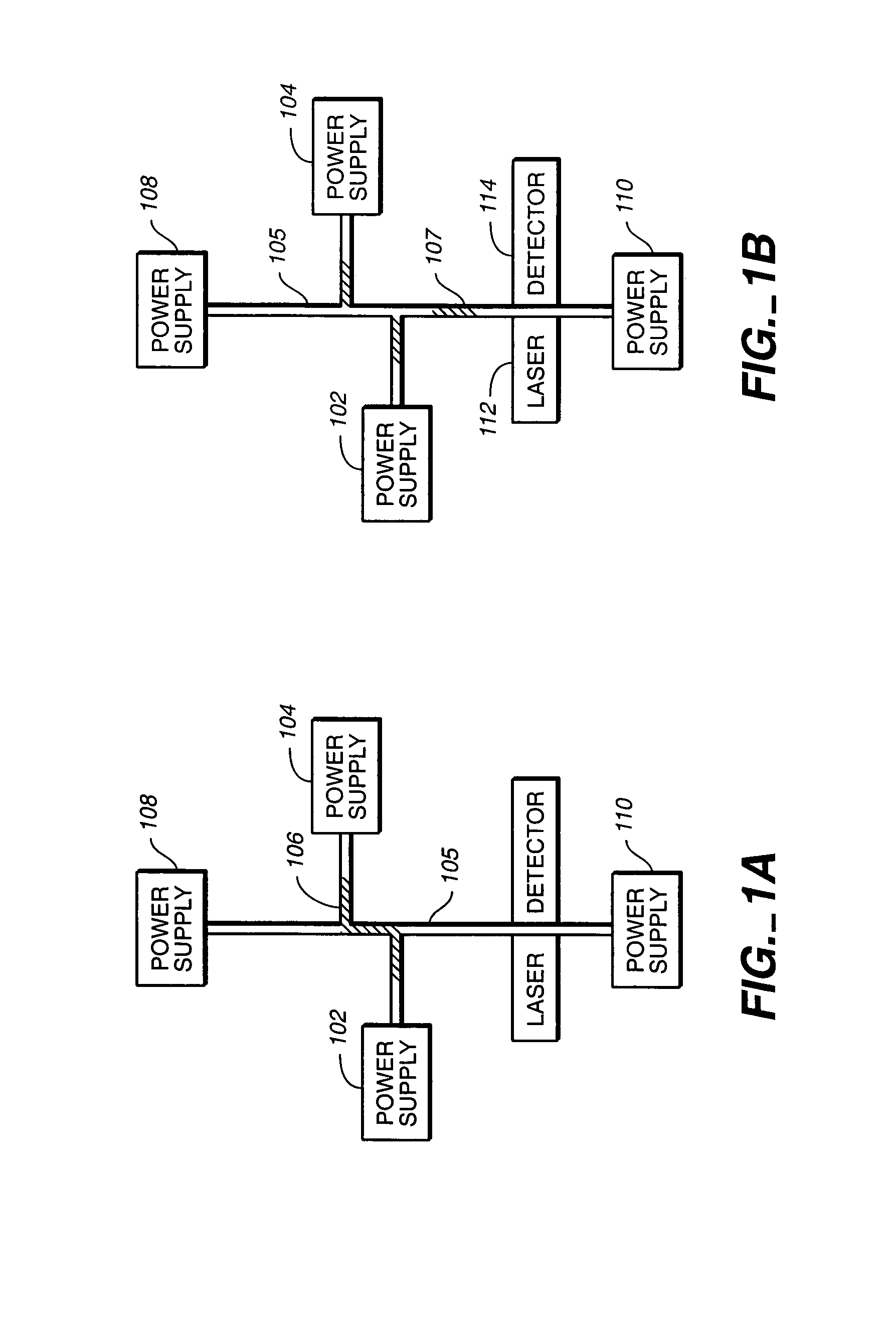
[0017]FIGS. 1A and 1B illustrate the use of a high voltage power supply of one embodiment of the present invention used in a microfluidics system. The electrokinetic pumping of fluids for chemical analysis requires a high voltage with a low current. Looking at FIG. 1A, the power supplies 102 and 104 are used to draw a sample 106 in a tube portion 105 between the power supplies, 108 and 110. For example, power supply 102 can be set to 900V and power supply 104 can be set 0V, while power supplies 108 and 110 are set to 300V or floated. Once the sample 106 is loaded into the tube portion 105, the power supplies 108 and 110 cause plug 107 to move down the tube 105. For example, power supply 110 can be set to 5000V and power supply 108 can be set to ground, while the power supplies 102 and 104 are set to 250V or floated. This causes plug 107 to move toward power supply 110. Based upon the weight or size of the components in the plug 107, different components take different amounts of tim...


PUM


Abstract

A high voltage power supply for use in a system such as a microfluidics system, uses a DC-DC converter in parallel with a voltage-controlled resistor. A feedback circuit provides a control signal for the DC-DC converter and voltage-controlled resistor so as to regulate the output voltage of the high voltage power supply, as well as, to sink or source current from the high voltage supply.

Description

REFERENCE TO RELATED APPLICATION[0001]This application is a divisional application of U.S. patent application Ser. No. 10 / 414,979, now U.S. Pat. No. 7,161,334, that was filed on Apr. 16, 2003.[0002]This invention was made with Government support under Contract No. DE— AC04-94AL85000 awarded by the U.S. Department of Energy to Sandia Corporation. The Government has certain rights to the invention, including a paid-up license and the right, in limited circumstances, to require the owner of any patent issuing in this invention to license others on reasonable terms.FIELD OF THE INVENTION[0003]The present invention relates to high voltage power supplies such as those used in microfluidic systems for chemical analysis.BACKGROUND[0004]Microfluidics is the science dealing with manufacturing and operating devices and processes using very small volumes of liquids. Microfluidics systems operate at such small scales that the system behavior is dramatically altered. For example, capillary action...

Claims


Application Information

Patent Timeline
Patent Type & Authority Patents(United States)
IPC IPC(8): G05F1/40G05F5/00
CPCH02M3/1584H02M3/1588Y02B70/1466Y02B70/10Y10S323/902
Inventor STAMPS, JAMES F.YEE, DANIEL D.
Owner NAT TECH & ENG SOLUTIONS OF SANDIA LLC
Why Eureka
Try Eureka