Connector mounting structure

a technology of connecting structure and connector, which is applied in the direction of couplings, machines/engines, mechanical equipment, etc., can solve the problems of complicated mounting work, scratching or damage of tubes, etc., and achieve the effect of easy connection operation of connectors and adjusting the function of mounting angl

Active Publication Date: 2008-07-22
SUMITOMO RIKO CO LTD
View PDF12 Cites 31 Cited by
  • Summary
  • Abstract
  • Description
  • Claims
  • Application Information

AI Technical Summary

Benefits of technology

[0010]A connector mounting structure according to the present invention to attain this object includes a structure in which, a fluid piping equipment such as a fuel pump and a fuel tank is provided with a connection hole, a retainer (for example, in a horseshoe, or approximately horseshoe shape) is held by a retainer holding portion formed in a vicinity of an opening of the connection hole, a connector is inserted into (for example, plugged in) the connection hole and prevented from dropping out via the retainer to thereby be mounted to the fluid piping equipment. The connector includes: a connecting portion having a cylindrical seal portion (for example, the other end portion in an axial direction) which is inserted into (for example, plugged in) the connection hole and sealed with respect to the connection hole by a seal member, and a flange stop portion formed on one end in an axial direction of the seal portion and engaged with the retainer in locked relation, a tube fitting portion (widely including a fitting portion of a tubular body for a fluid such as a tube and a hose) formed on one end in the axial direction of the connecting portion in a bending state. A positioning means is disposed between the connecting portion of the connector and the fluid piping equipment. The positioning means has a first engaging portion provided in the connecting portion of the connector and a second engaging portion provided in the fluid piping equipment. The positioning means is to position the connector or the connecting portion of the connector in a circumferential direction so as not to rotate relative to the connection hole by engaging the first engaging portion and the second engaging portion in the circumferential direction. The positioning means has a mounting angle adjusting function capable of positioning the connecting portion in the circumferential direction selectively at any one of a number of mounting angular positions (mounting angular positions in the circumferential direction) relative to the connection hole. An annular surface on the other end in the axial direction of the stop portion is formed in a taper shape tapered toward the other end in the axial direction. Owing to the mounting angle adjusting function, it becomes possible to position the connecting portion in a circumferential direction, for example, respectively at a number of mounting angular positions of three positions or more, or for example, respectively at a number of mounting angular positions of four, five, six positions or more. The connecting portion or the seal portion of the connector may be inserted to be connected to an annular connection hole. Besides, the first engaging portion and the second engaging portion are engaged in the circumferential direction, for example, in response to insertion of the connecting portion or the seal portion of the connector into the connection hole.
[0012]In the present invention, the retainer held by the retainer holding portion is engaged with the flange stop portion in locked relation, and thereby, the connector of which connecting portion is inserted into the connection hole is prevented from dropping out relative to the fluid piping equipment. The stop portion is formed, for example, to have a larger outside diameter (larger outer diameter) than the seal portion. The retainer is formed, for example, in a horseshoe shape or approximately horseshoe shape to have a pair of engaging arms. However, if the annular surface on the other end in the axial direction of the stop portion is formed in a taper shape tapered toward the other end in the axial direction, it becomes possible to have a constitution in which the retainer or the engaging arms may not becomes an intervention for the insertion of the connecting portion or the seal portion into the connection hole, even if the retainer is held in the retainer holding portion in advance so that, for example, the engaging arms may position in a passage of the stop portion. The connecting portion or the seal portion of the connector is, for example, inserted into the connection hole passing between the pair of engaging arms of the retainer. The annular surface on the other end in the axial direction of the stop portion passes between the engaging arms, for example, so as to press to widen an interval of the pair of the engaging arms, when the connecting portion or the seal portion is inserted into the connection hole. The retainer constitutes a stop structure by being positioning, for example, between the stop portion and the retainer holding portion. The retainer is, for example, held by the retainer holding portion so as not to move in a direction in which the connector is dropped out of the connection hole.
[0013]It is possible to form the pair of the engaging arms of the retainer so as to be snap engaged with the annular surface on one end in the axial direction of the stop portion when the stop portion passes through the engaging arms, to secure an easy and certain stop function of the connector. Further, it is effective that the seal portion or the seal member has a smaller outside diameter than the interval between the pair of engaging arms of the retainer (the interval when a force to press to widen does not act).
[0015]The retainer holding portion can be formed in an annular body or approximately annular body with a through-hole. Besides, it can be constituted so that the seal portion and the stop portion pass inside of the retainer holding portion (through hole) in the annular body or approximately annular body, when the seal portion is inserted into the connection hole. In case of such a constitution, it is preferable that the second engaging portion, engaging with the first engaging portion provided in the outer periphery of the connecting portion of the connector, is provided in the through hole of the retainer holding portion so that the inserting connection operation of the connector becomes easy. Bedsides, it is effective that the first engaging portion is provided in the outer periphery of the connecting portion, and on one end in the axial direction with respect to the stop portion.
[0016]To secure a certain rotation stop function or anti-rotation function with an easy constitution, one of the first engaging portion and the second engaging portion is formed as an engaging protruding portion, and the other is formed as an engaging recessed portion capable of fitting on the engaging protruding portion. Namely, it is possible that the first engaging portion is made to be the engaging protruding portion or the engaging recessed portion, and the second engaging portion is made to be the engaging recessed portion or the engaging protruding portion fitting to this first engaging portion to engage therewith in the circumferential direction. Besides, the engaging recessed portions are arranged, for example, in an annular state or in a circular state, and provided more than the number of the engaging protruding portion (one or more), and thereby the mounting angle adjusting function can be constituted. For example, the first engaging portion is set to be the engaging protruding portion, the second engaging portion is set to be the engaging recessed portion fitting on this engaging protruding portion to engage therewith in the circumferential direction, and the engaging recessed portions are provided more than the number of the engaging protruding portions along the circumferential direction in the through hole of the retainer holding portion, and then, a mounting angle adjustment of the tube fitting portion can be performed easily by selecting the engaging recessed portion with which the engaging protruding portion is fitted to be engaged. Incidentally, for example, when a plurality of the engaging protruding portions are arranged, equally spaced in the circumferential direction, the number of the engaging recessed portion may be equal to or more than the number of the engaging protruding portions. The mounting angle of the tube fitting portion can be adjusted effectively with the constitution as stated here. The number of the engaging recessed portion may be equal to or more than the number of the engaging protruding portion.
[0017]According to the connector fixing structure of the present invention, it is possible to position the tube fitting portion extending in an appropriate direction when the connector is mounted, and a complex arranging operation of the retainer becomes unnecessary.

Problems solved by technology

However, when the quick connector is mounted to the fuel pump in a rotatable state, and a direction in which the tube fitting portion is extending can be variable, there is a possibility that the tube swings to be in contact or abut with peripheral parts to cause the tube to be scratched or damaged, when a pressure of an inner fluid flowing in the tube may be fluctuated or an impact may be added from a vehicle body side.
Besides, in the connector mounting structure described in the Patent Document 1, the retainer is mounted to the retainer holding portion after the quick connector is inserted into the connection hole, in order to prevent the quick connector from dropping out, and therefore, a mounting work is complicated.

Method used


Image

  • Connector mounting structure
  • Connector mounting structure
  • Connector mounting structure

Examples


Embodiment Construction

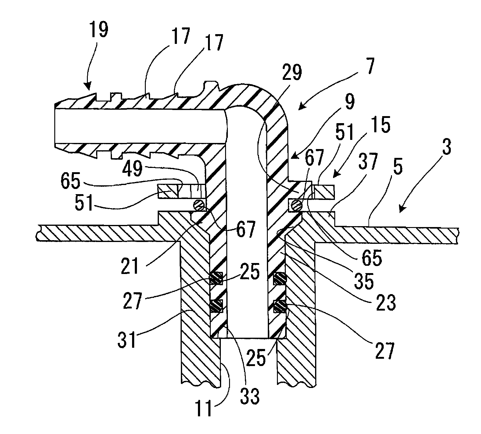
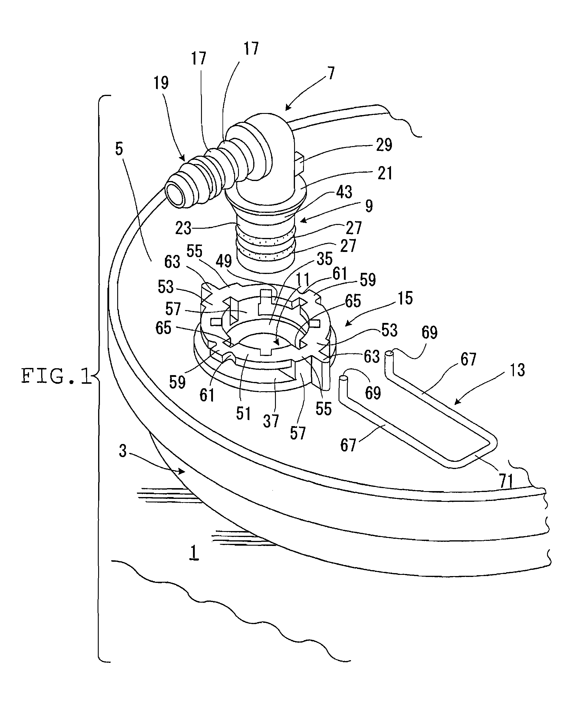
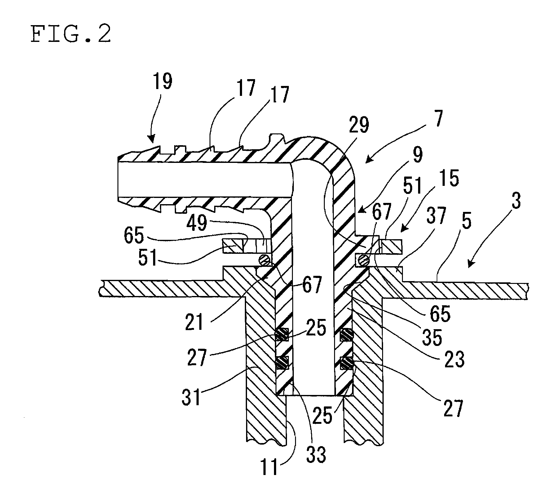
[0025]In the connector mounting structure in FIGS. 1 to 4, a connection hole 11 into which a connecting portion 9 of a cylindrical quick connector 7 is inserted, is formed on a cap 5 of a fuel pump 3 attached to a fuel tank 1 of a motor vehicle, and a retainer holding portion 15 to hold a wire retainer (wire member retainer) 13 is integrally provided around an opening of this connection hole 11.

[0026]The quick connector 7 has a tube fitting portion 19 formed on one side in an axial direction (outside of the axial direction) of the connecting portion 9 in a state bending 90 degrees, namely in a state bending just laterally, in which a number of annular stop protrusions 17 are provided on an outer periphery, and integrally is formed by using resinous material such as fiber reinforced PA (polyamide) or fiber reinforced POM (polyacetal). An annular stop portion 21 in an outward flange state or in a flange state is integrally provided at a center in the axial direction of the cylindrical...


PUM


Abstract

A connector is inserted into a connection hole provided on a fluid piping equipment, and the connector is prevented from dropping out via a retainer held by a retainer holding portion. The connector has a connecting portion including a flange stop portion, and a positioning means is disposed between the connecting portion and the fluid piping equipment. This positioning means is to position the connecting portion in a circumferential direction so as not to rotate relative to the connection hole and has a mounting angle adjusting function capable of positioning the connecting portion in the circumferential direction selectively at any one of a number of mounting angular positions relative to the connection hole. An annular surface on the other end in the axial direction of the stop portion is formed in a taper shape tapered toward the other end in the axial direction.

Description

BACKGROUND OF THE INVENTION[0001]1. Field of the Invention[0002]The present invention relates to a mounting structure of a connector used for a fluid piping connection of a motor vehicle and so on, and for example, to a connector mounting structure mounting a connector for coupling a tube to a fuel pump of the motor vehicle.[0003]2. Description of the Related Art[0004]A tube for constituting a gasoline fuel piping is coupled to a fuel pump provided on a gasoline fuel tank of a motor vehicle. The communication of the tube with the fuel pump is performed in a mode as stated below: a connection hole is formed in a cap of the fuel pump, and a quick connector to which the tube is fitted to be connected is inserted into the connection hole and mounted to the cap. As the quick connector for coupling the fuel pump and the tube, the one is used in which a tube fitting portion is integrally formed in a bending state on one end in an axial direction of a cylindrical connecting portion, and, on...

Claims


Application Information

Patent Timeline
Patent Type & Authority Patents(United States)
IPC IPC(8): F16L19/00
CPCF16L37/088F02M55/00F16L37/144F02M2200/8023F16L37/0885
Inventor NIKI, NOBUAKI
Owner SUMITOMO RIKO CO LTD
Why Eureka
Try Eureka