Recording apparatus

a recording apparatus and recording medium technology, applied in the field of recording apparatuses, can solve the problems of increased costs and difficulty in ensuring conveyance accuracy, and achieve the effect of improving the image quality of the recorded image and improving the conveyance accuracy of the recording medium

Inactive Publication Date: 2008-07-22
CANON KK
View PDF39 Cites 14 Cited by
  • Summary
  • Abstract
  • Description
  • Claims
  • Application Information

AI Technical Summary

Benefits of technology

[0008]The present invention has been achieved in view of the above described technical problems, and has an object to provide a recording apparatus that is compact and inexpensive, and can improve conveyance accuracy of a recording medium in a conveying mechanism portion.
[0011]According to the present invention, the drive amount detecting means is provided for detecting the drive amount of the drive transmitting means for connecting the conveying means provided upstream of the recording portion and the conveying means provided downstream of the recording portion so as to be able to perform drive transmission. Thus, a control constant of the drive means is made variable according to a position of the recording medium, thereby providing a compact and inexpensive apparatus, improving conveyance accuracy of the recording medium in the conveying mechanism portion, and improving image quality of a recorded image.

Problems solved by technology

However, the method of reducing the diameter of the conveying roller makes it difficult to ensure conveyance accuracy, and thus either a method of increasing a diameter of the code wheel to increase the resolution or a method of increasing resolution of an encoder only can be used, both of which increase costs.
Second, reducing the conveyance resolution to increase the resolution may affects a reduction ratio from a conveying motor to the conveying roller to prevent an optimum RPM of the motor or optimum motor torque from being chosen in selecting the conveying motor.

Method used


Image

  • Recording apparatus
  • Recording apparatus
  • Recording apparatus

Examples


Embodiment Construction

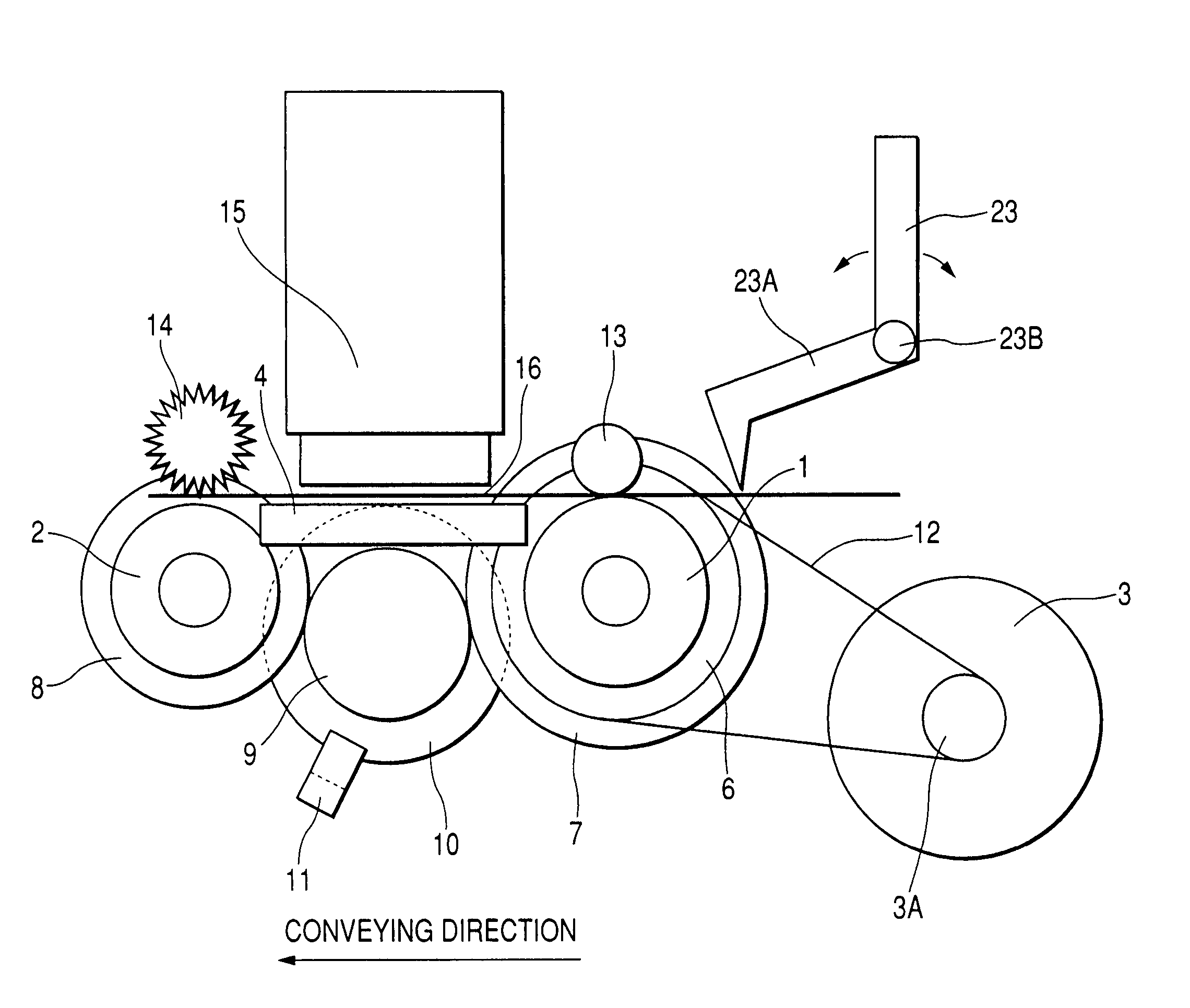
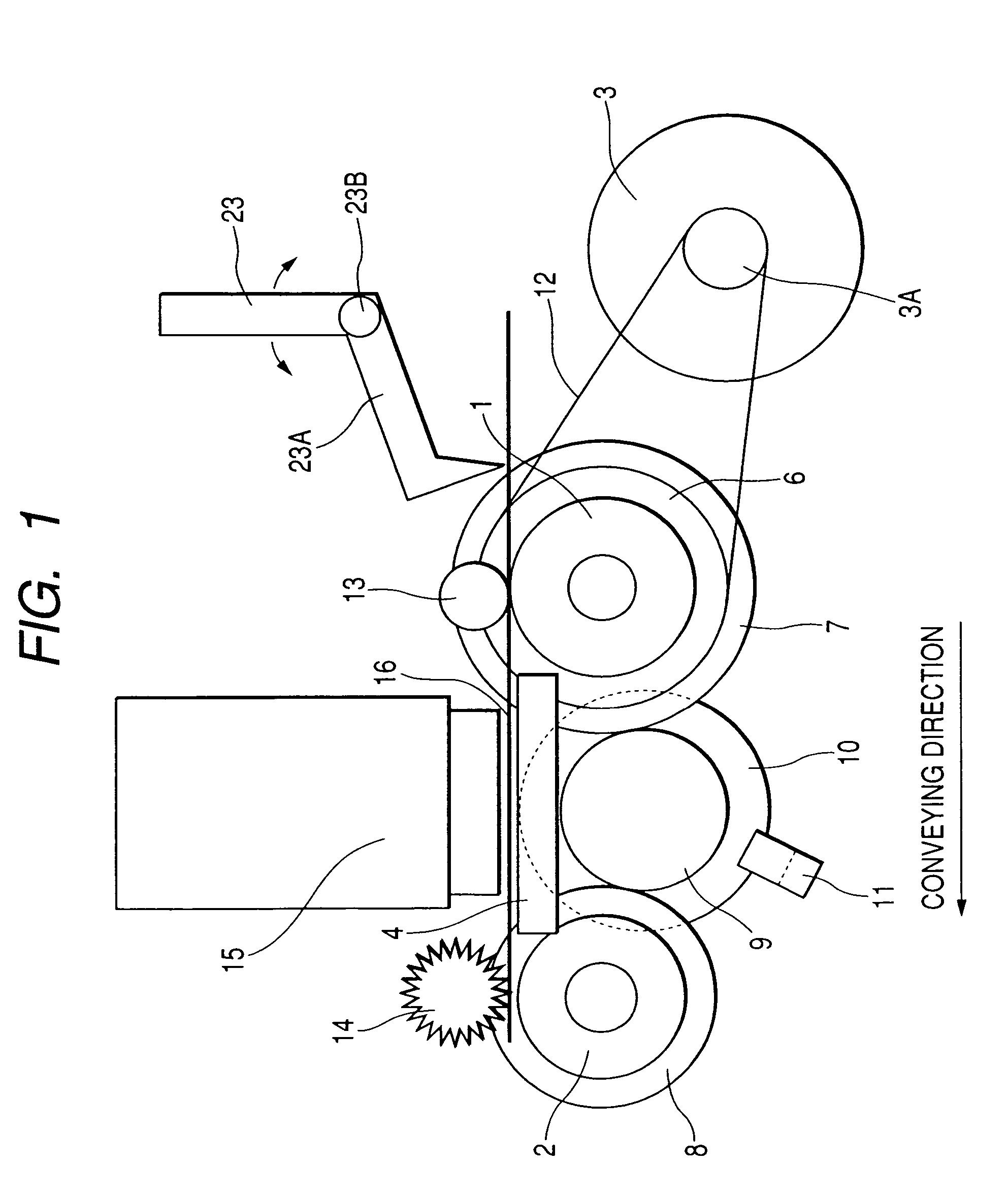
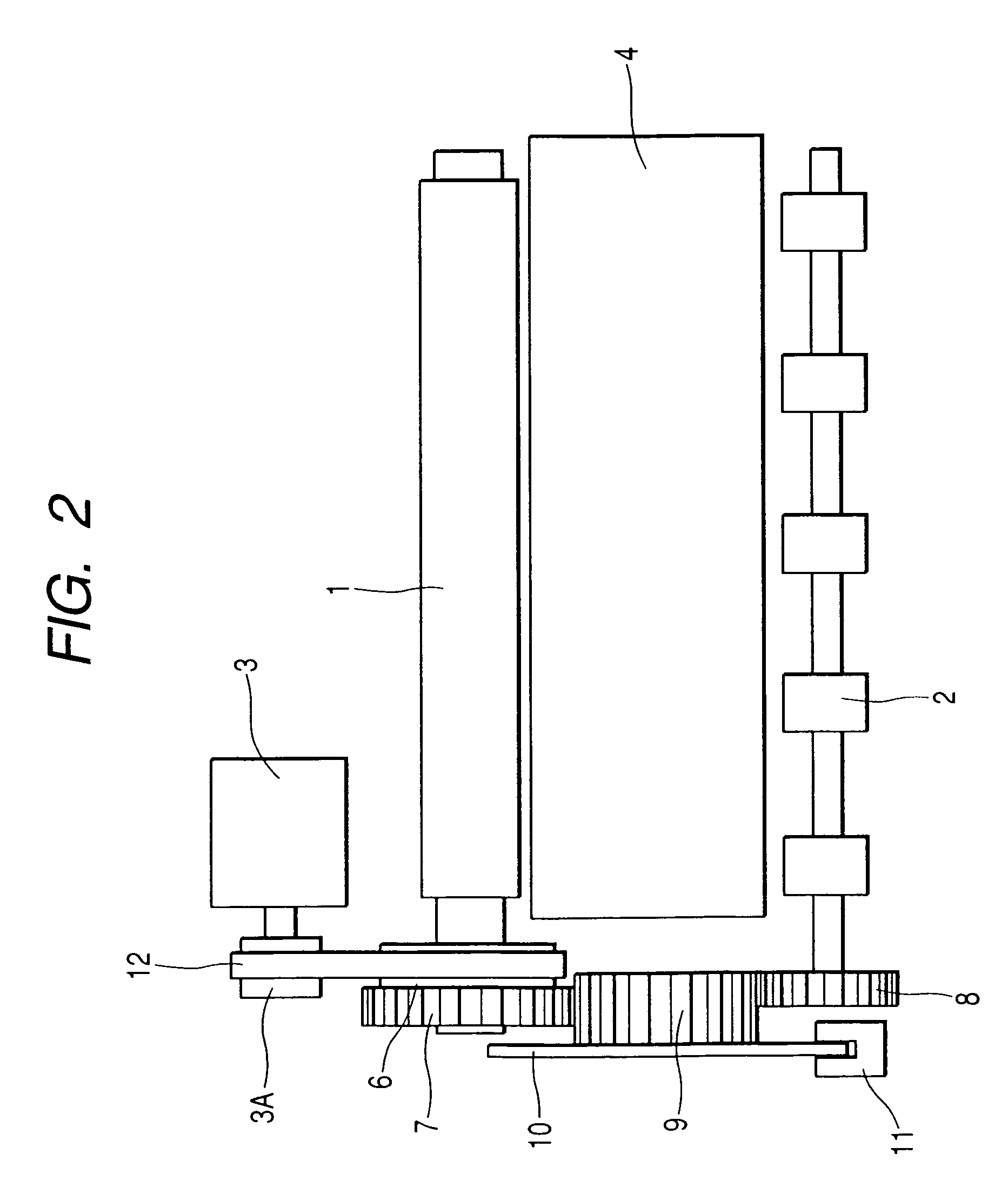
[0015]Now, an embodiment of the present invention will be described in detail with reference to the drawings. The same reference numerals denote the same or corresponding parts throughout the drawings. FIG. 1 is a schematic side view of essential portions of a recording apparatus according to an embodiment of the present invention, FIG. 2 is a schematic plan view of a configuration on a lower side from a recording medium of the recording apparatus in FIG. 1, and FIG. 3 is a block diagram of a control system of the recording apparatus in FIG. 1. In FIGS. 1 and 2, reference numeral 1 denotes a conveying roller (an LF roller) as conveying means (a first conveying roller) provided upstream of a recording portion (upstream in a conveyance direction), which is constituted by a metal roller coated with alumina powder with urethane resin or the like in the embodiment.

[0016]Reference numeral 13 denotes a pinch roller, which is pressed on the conveying roller 1 by unshown urging means to form...


PUM


Abstract

A conveying roller and a paper expelling roller provided upstream and downstream, respectively, of a recording portion in a conveyance direction are connected via an idler gear so as to be able to perform drive transmission, a rotation drive amount of the idler gear is detected, ends of a recording medium in the conveyance direction are detected, driving of a conveying motor is controlled based on detection signals of the rotation drive amount of the idler gear and the ends of the recording medium, and a control constant is made variable according to a position of the recording medium in the conveyance direction.

Description

BACKGROUND OF THE INVENTION[0001]1. Field of the Invention[0002]The present invention relates to a recording apparatus for recording on a recording medium conveyed by a conveying mechanism portion using recording means.[0003]2. Related Background Art[0004]As output apparatuses of various information processing apparatuses including personal computers, recording apparatuses have been used for recording on a recording medium using recording means based on recording information, such as printers, image forming apparatuses, facsimiles, or copiers. The recording apparatuses are classified into thermal transfer recording apparatuses, inkjet recording apparatuses, laser recording apparatuses, wire dot recording apparatuses, or the like according to the kinds of the recording apparatuses. The recording apparatuses are adapted for recording on a recording medium conveyed by a conveying mechanism portion, and classified into apparatuses of a serial type for recording while performing main sca...

Claims


Application Information

Patent Timeline
Patent Type & Authority Patents(United States)
IPC IPC(8): B41J2/01B41J11/42B41J13/00B41J19/78
CPCB41J13/0027B41J11/425
Inventor NISHIBERI, NOZUMUONUMA, KENTAROSAITO, HIROYUKI
Owner CANON KK
Why Eureka
Try Eureka