Programmable logic circuit and method of using same

a logic circuit and program technology, applied in the direction of semiconductor devices, semiconductor/solid-state device details, instruments, etc., can solve the problems of inability to optimize the architecture of the microprocessor for any one application, the power consumption of the typical microprocessor is typically less than that and the typical application efficiency of the typical microprocessor is relatively inefficient, so as to achieve the effect of little area devoted to the control ga

Active Publication Date: 2008-07-22
AXON TECH
View PDF4 Cites 61 Cited by
  • Summary
  • Abstract
  • Description
  • Claims
  • Application Information

AI Technical Summary

Problems solved by technology

Because the microprocessors are typically designed to be used for a variety of applications, the architecture of the microprocessor cannot generally be optimized for any one application.
Thus, the typical microprocessor is relatively inefficient for a specific application, compared to a microprocessor designed for that specific application.
Such circuits also typically require fewer transistors to perform their intended function, compared to traditional microprocessors, and thus power consumption of these processors is typically less compared to typical microprocessors.
Although custom or semi-custom processors can perform their intended functions faster and with less power, compared to traditional microprocessors, the custom processors are generally expensive to design and manufacture and require additional design time.
Thus, these processors are typically only used where large volumes of the same processor are required, such that the increased cost of the microprocessor can be recouped.
Use of multiple processors in a single appliance results in reduced power efficiency.
Thus, many of the benefits associated with custom microprocessors may be lost in applications where more than one microprocessor is required.
However, the use of the memory-controlled connecting components for the circuit routing makes FPGAs considerably slower than application-specific circuits, for the same applications.

Method used


Image

  • Programmable logic circuit and method of using same
  • Programmable logic circuit and method of using same
  • Programmable logic circuit and method of using same

Examples


Embodiment Construction

[0035]The present invention generally relates to programmable logic circuits. More particularly, the invention relates to circuits including reconfigurable memory elements. The elements and circuits of the present invention can be used in a variety of applications and can replace traditional and application-specific processors in a variety of systems.

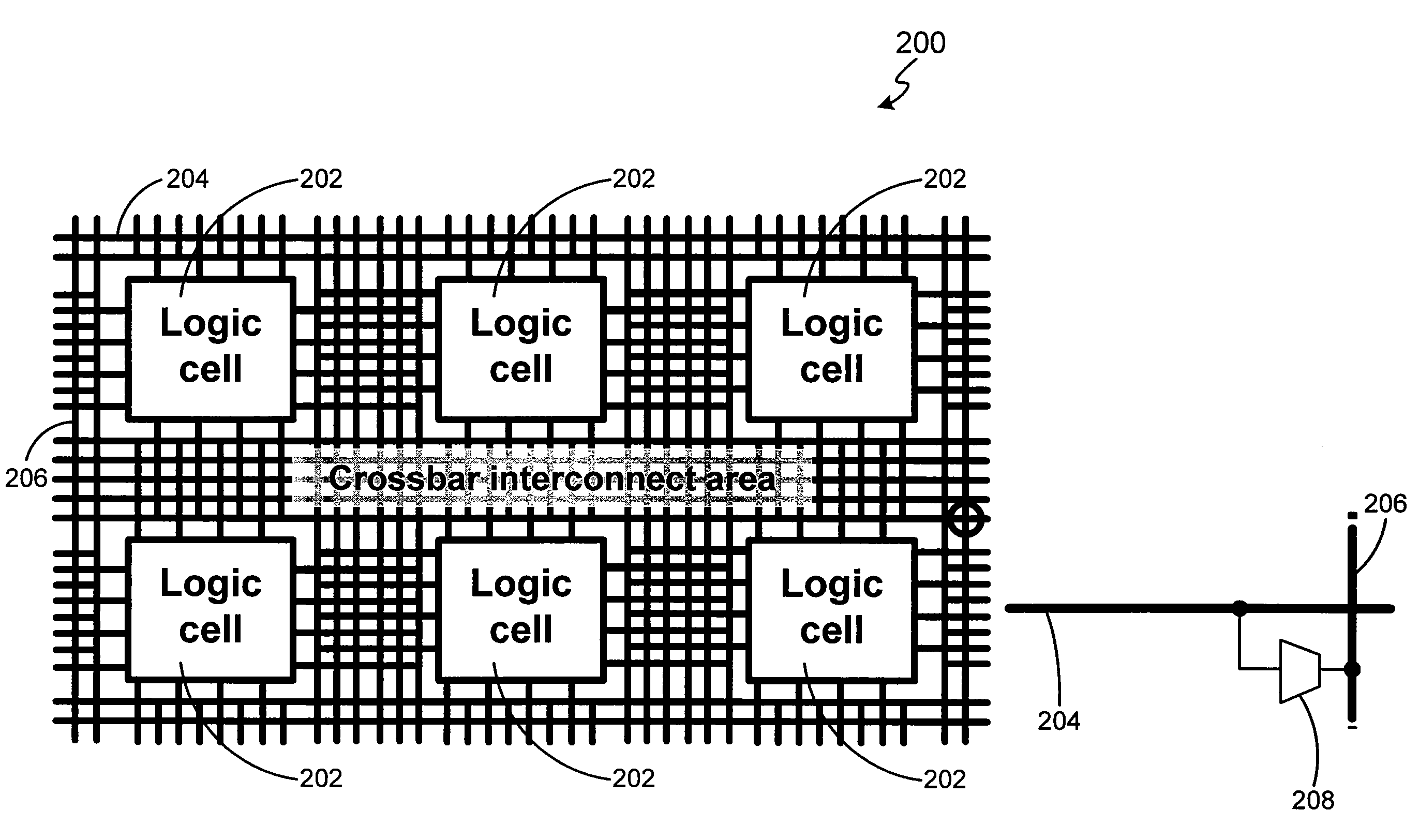
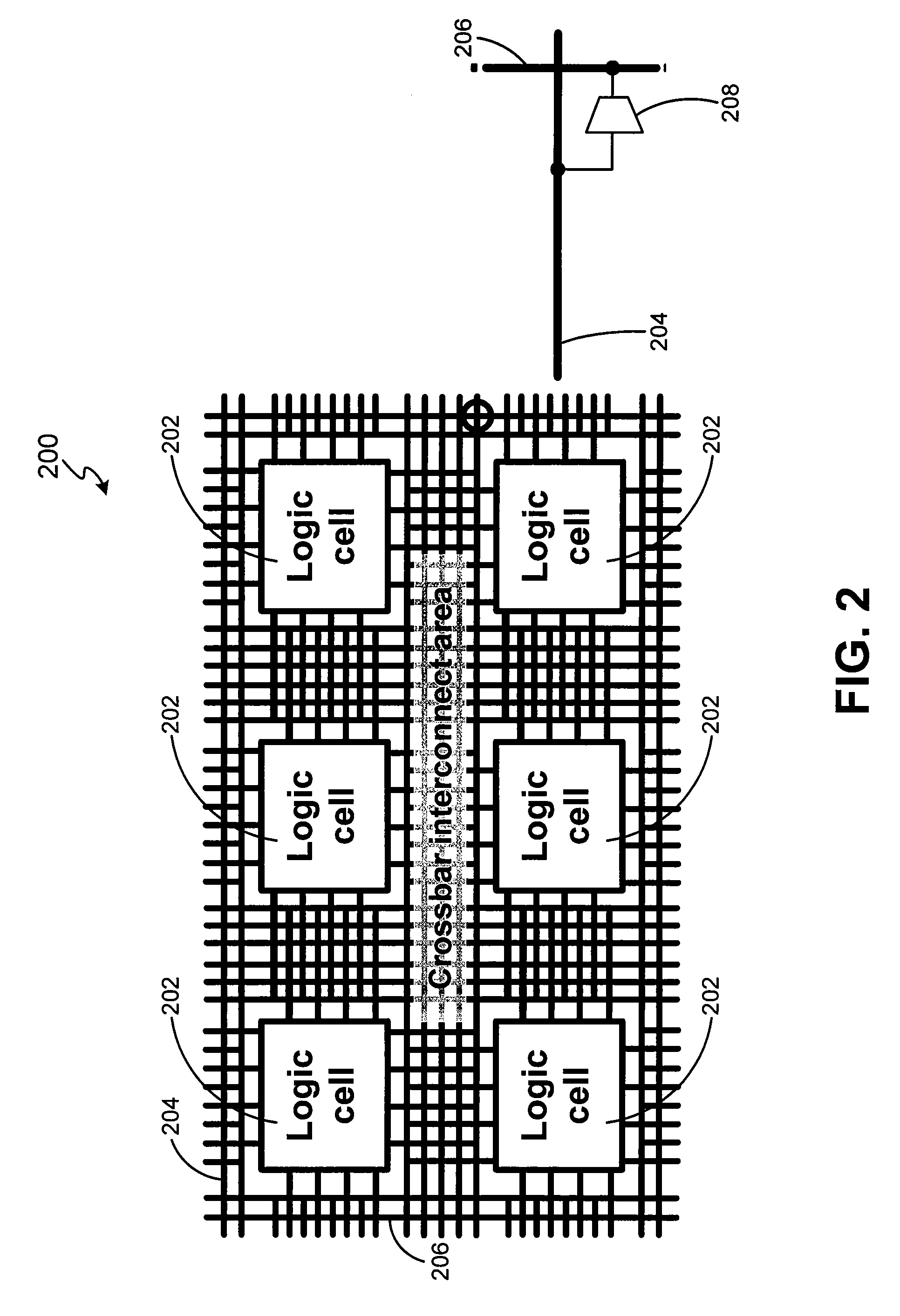
[0036]FIG. 2 illustrates a portion of a programmable logic circuit 200 in accordance with exemplary embodiments of the present invention. Circuit 200 includes a plurality of logic cells 202 coupled together with electrical wires configured in rows 204 and columns 206, and programmable elements 208. Cells 202 and wires 204, 206 may include any circuits and wires known in the art, such as those used in circuit 100.

[0037]Programmable elements 208 are inserted at the intersection of various row and columns to allow reconfiguration of circuit 200. Programmable element 208 may act as both a switch, to couple or decouple various rows and colum...


PUM


Abstract

A programmable logic circuit, including programmable memory element, suitable for microprocessor applications, and a method of using the circuit are disclosed. The programmable circuit includes at least one logic cell, columns and rows of wires coupled to the logic cell, and a programmable memory element located at the intersection of two wires. The programmable element acts as a switch and as memory for the logic circuit.

Description

CROSS REFERENCE TO RELATED APPLICATIONS[0001]This application claims the benefit of U.S. patent application Ser. No. 60 / 670,845, entitled USE OF PROGRAMMABLE CELL DEVICES IN RECONFIGURABLE LOGIC APPLICATIONS, filed Apr. 13, 2005, the contents of which are incorporated herein by reference.FIELD OF INVENTION[0002]The present invention generally relates to program logic circuits and systems, and more particularly, to programmable logic circuits including programmable switch and programmable memory elements.BACKGROUND OF THE INVENTION[0003]Microprocessors have long been used in a wide variety of applications, such as computers, automobiles, appliances, and hand-help devices such as cameras, personal digital assistants (PDAs) and cell phones. Often times, the same microprocessor type is used for several such applications by using software that is specific for the application. Because the microprocessors are typically designed to be used for a variety of applications, the architecture of ...

Claims


Application Information

Patent Timeline
Patent Type & Authority Patents(United States)
IPC IPC(8): H01L27/10
CPCH01L27/118H01L27/11807H01L27/2463H01L27/2481H01L45/085H01L45/146H01L45/1266H01L45/14H01L45/142H01L45/143H01L45/144H01L45/1233H01L27/101H10B63/80H10B63/84H10N70/245H10N70/8416H10N70/826H10N70/8822H10N70/881H10N70/8825H10N70/8828H10N70/8833
Inventor KOZICKI, MICHAEL NMITKOVA, MARIAGOPALAN, CHAKRAVARTHYBALAKRISHNAN, MURALIKRISHNAN
Owner AXON TECH
Why Eureka
Try Eureka