Series interleaved boost converter power factor correcting power supply

a technology of power factor and converter, applied in the field of power supplies, can solve the problems of significant current demand on a source of input power, unsatisfactory low power factor, and power factor reduction, and achieve the effect of improving power factor and power factor

Active Publication Date: 2008-07-22
HARMAN INT IND INC
View PDF33 Cites 79 Cited by
  • Summary
  • Abstract
  • Description
  • Claims
  • Application Information

AI Technical Summary

Benefits of technology

[0015]The input stage power converter includes a plurality of boost switches that are coupled in series. The boost switches are also configured to be coupled in parallel across an AC input voltage. The AC input voltage provided to the boost switches may be a rectified AC input voltage or may be an un-rectified AC input voltage. The input stage power converter also includes a power factor correction (PFC) controller. The boost switches may be independently controlled by the PFC controller to perform power factor correction and voltage regulation of the DC output voltage. The boost switches are switched at high frequency with series interleave by the PFC controller to reduce ripple current and improve power factor.
[0018]The sinusoidal waveform of the PWM voltage (Vc) may be generated by the PFC controller with the boost switches to improve the power factor. The average amplitude of the PWM voltage (Vc) waveform is controlled to be substantially similar to the amplitude of the waveform of the AC input voltage (Vin). The AC current waveform may therefore be maintained substantially in phase with the waveform of the AC input voltage (Vin) and power factor is improved. The duty cycle of the boost switches is further controlled by the PFC controller to compensate for a range of magnitudes of AC input voltage (Vin), such as from about 90 VAC to about 265 VAC. The AC input voltage (Vin) may be used to produce a total boost voltage (Vboost), such as about 380 to 400 VDC.

Problems solved by technology

Such non-linear power electronic loads typically include rectifier / capacitor input stages that are characterized by an undesirably low power factor due to excessive load current harmonics.
Harmonic currents result in a reduction in power factor since harmonic currents do not provide useful power to the non-linear power electronic load.
Multiple kilowatt non-linear power electronic loads, such as a high power audio amplifier or a magnetic resonance imaging gradient amplifier, place significant current demands on a source of input power.
When a load with a low power factor is present, the RMS current requirement is higher, and the circuit breaker may open the power feed even though the load is not productively utilizing substantial power.
The higher switching frequencies may result in undesirably high levels of ripple frequencies (e.g. distortion).
At light loads, however, equal voltage may not be produced across the capacitors.
The voltage imbalance may result in unbalanced operation of the three level boost converter resulting in stress on the boost sub-circuits.
The reduced magnitude of ripple current, however, still creates undesirable load currents.
In addition, with the previously discussed unbalanced conditions of the three-level boost converter, reduction in ripple current may be adversely affected due to incomplete ripple cancellation.

Method used


Image

  • Series interleaved boost converter power factor correcting power supply
  • Series interleaved boost converter power factor correcting power supply
  • Series interleaved boost converter power factor correcting power supply

Examples


Embodiment Construction

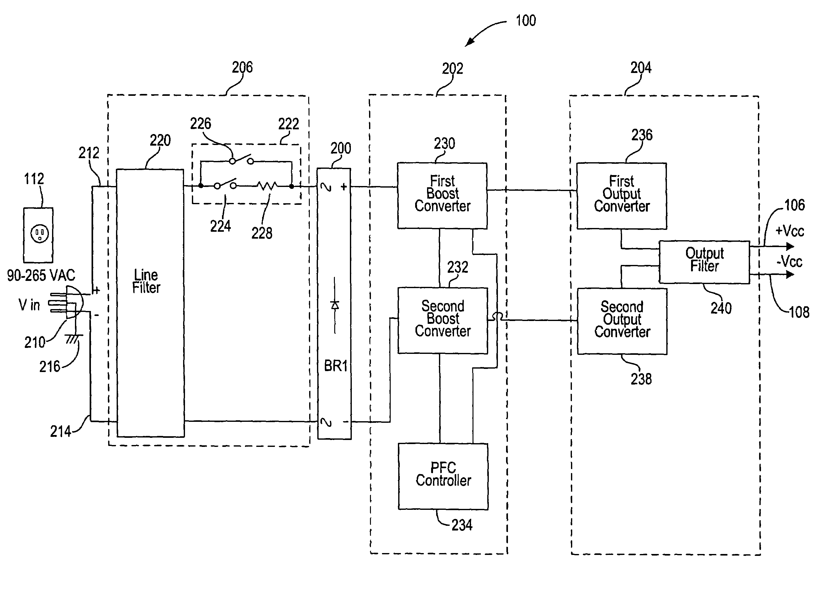
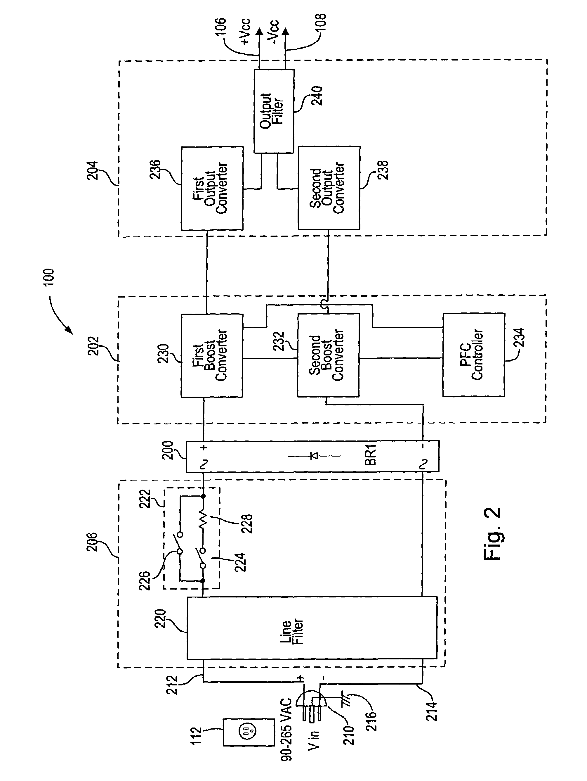
[0040]This invention includes a power factor correcting power supply. The power factor correcting power supply provides a regulated output voltage(s) using high efficiency switch mode operation. In addition, the power supply minimizes harmonics and ripple current. The power supply operates as a non-linear power electronic load with power factor correction (PFC) to increase the input power factor towards unity.

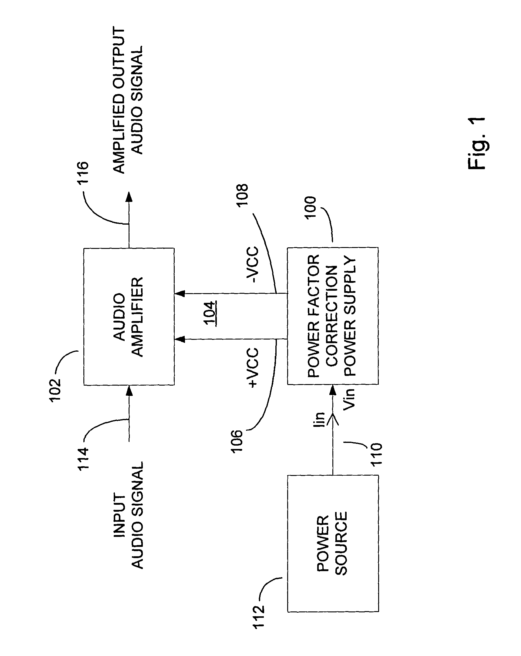
[0041]FIG. 1 is a block diagram of a power factor correcting power supply 100 in an example application supplying regulated DC voltage to an audio amplifier 102. The power factor correcting power supply 100 provides output power on one or more output power lines 104. In the illustrated example, the output power lines 104 include a positive DC output voltage (+Vcc) provided on a positive DC rail 106, and a negative DC output voltage (−Vcc) provided on a negative DC rail 108. Other examples of the power factor correcting power supply 100, may include fewer or greater numbers of o...


PUM


Abstract

A power factor correcting power supply includes an input stage power converter and an output stage power converter. The input stage power converter includes a plurality of series connected boost switches and a power factor correction controller. The power factor correction controller may direct the operation of the boost switches with series interleave phasing to perform power factor correction and voltage regulation. The boost switches are supplied input voltage and input current from a power source. The input voltage is converted to a DC boost voltage by high frequency series interleaved switching of the boost switches. The DC boost voltage is converted to a DC output voltage by the output stage power converter. The DC output voltage is provided on a DC rail for a load of the power factor correcting power supply.

Description

[0001]The following commonly owned U.S. patent is related to this application: U.S. Pat. No. 6,949,915, issued Sep. 27, 2005, entitled OPPOSED CURRENT CONVERTER POWER FACTOR CORRECTING POWER SUPPLY.BACKGROUND OF THE INVENTION[0002]1. Technical Field[0003]The invention generally relates to power supplies and, more particularly, to a power supply that performs power factor correction with series interleaved phasing.[0004]2. Related Art[0005]Power supplies are utilized as a source of power in many electrical devices including most devices having electronic circuits. A power supply may utilize input power from a single phase or a multiple phase alternating current source to produce output power. The output power may be produced at one or more predetermined voltages with a determined range of output current. The output power may be alternating current (AC) or direct current (DC) of almost any magnitude depending on the load the power supply is serving.[0006]Some power supplies and associ...

Claims


Application Information

Patent Timeline
Patent Type & Authority Patents(United States)
IPC IPC(8): H02M3/335H02M1/00H02M1/42H02M7/12H02M3/155H02M3/28H02M7/219
CPCG05F1/70H02M7/219H02M1/4208Y02B70/126Y02B70/10
Inventor STANLEY, GERALD R.
Owner HARMAN INT IND INC
Why Eureka
Try Eureka